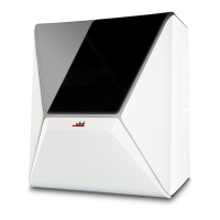
FIG. 143 APPROXIMATE REPRESENTATION OF THE MAXIMUM
EXTENSION
12. Remove the upper service cover, the safety cover
and, if necessary, the spindle unit.
Exchanging the spindle unit – on page66
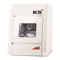
13. In the area behind the upper service cover, use the
TX25 angle screwdriver to loosen the 12 screws
that secure the bellow frame.
n
To reach each screw, carefully move the
spindle unit several times or, if the spindle
unit is removed, move the spindle holder by
hand in the X and Y directions.
n
To loosen the middle left screw (marked
green), it must be in the recess.
FIG. 144
FIG. 145
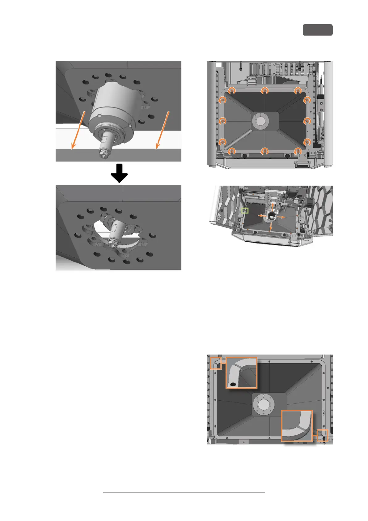
14. Pull the bellow upwards out of the machine.
Particularly if you have not removed the spindle
unit, note the following:
n
Tilt the front part of the bellow up and the
rear part down.
n
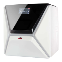
The frame of the bellow in two parts. Lift the
frame ends at the front left and rear right
(bottom left and top right in the figure) and
move them inward. This allows you to rotate
the bellow and move the rear part past the
bottom of the spindle unit.
FIG. 146 ENDS OF THE TWO-PART FRAME MARKED IN ORANGE
Maintenance
EN 61
Original Operating Instructions: E5
Version: 4/27/2023