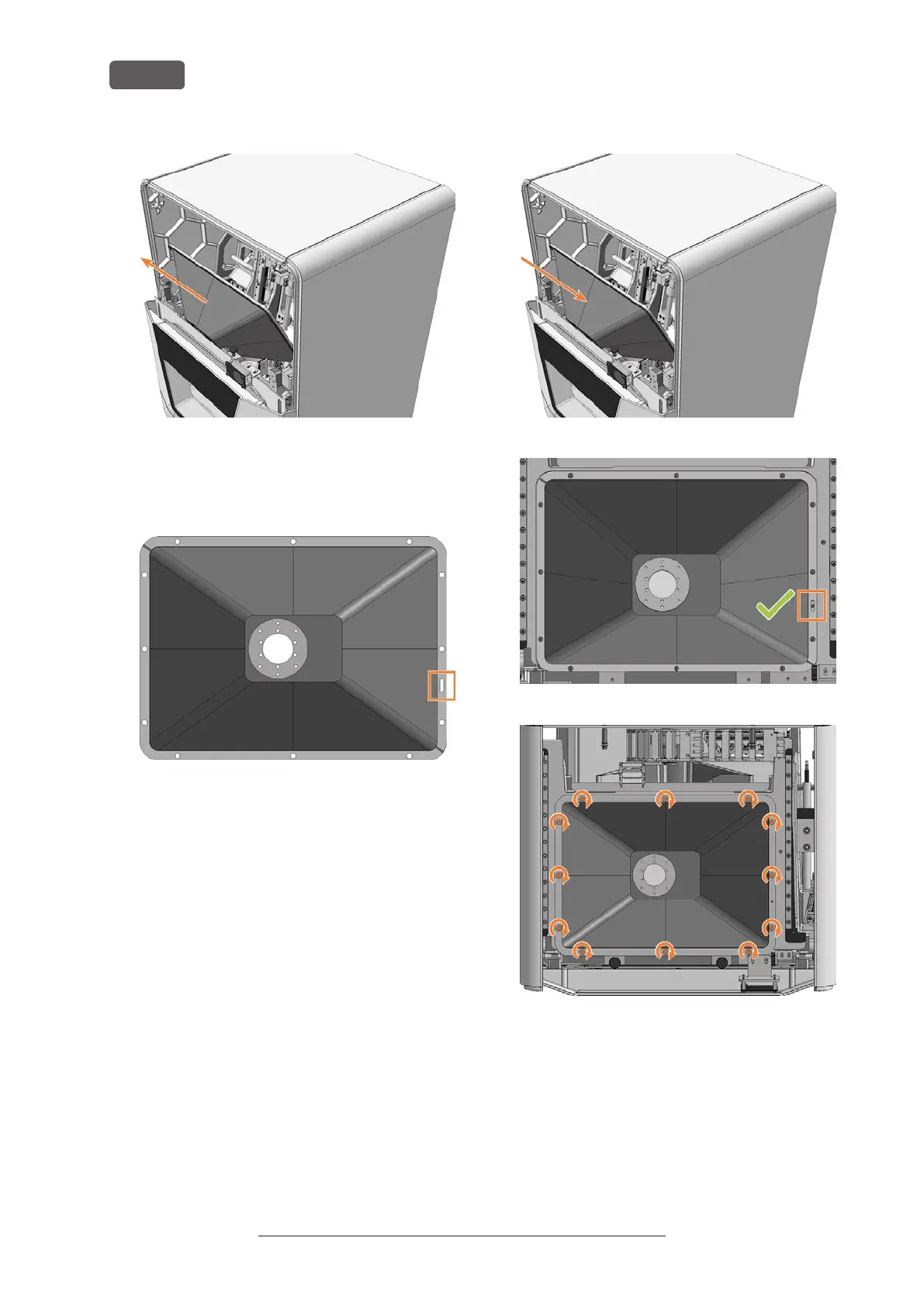
FIG. 147
15. Align the spare bellow so that the opening for the
positioning pin (marked orange) in the frame is on
the right-hand side.
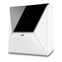
FIG. 148 TOP VIEW OF SPARE BELLOW: OPENING FOR THE
POSITIONING PIN (MARKED ORANGE)
16. Insert the bellow into the machine. The positioning
pin must be in the corresponding opening in the
frame.
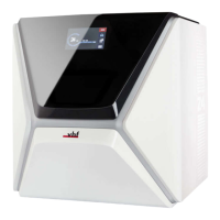
17. Use the TX25 angle screwdriver to tighten the
frame of the bellow with 12 screws.
FIG. 149
FIG. 150 POSITIONING PIN IN OPENING (MARKED ORANGE)
FIG. 151
18. If necessary, install the spindle unit.
Exchanging the spindle unit – on page66
19. Install the upper safety cover and service cover.
20. Open the working chamber door using the emer-
gency release.
Emergency opening of the working chamber door –
on page99
Original Operating Instructions:E5
Version: 4/27/2023
Maintenance
EN 62