FIG. 154 SPINDLE SHOWN IN HIGHER POSITION FOR CLARITY
FIG. 155
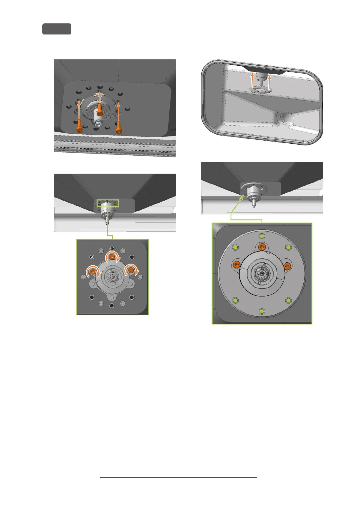
24. Slide the mounting washer up over the spindle
until it is properly seated on the bellow:
n
The heads of the 3 screws (marked orange)
that you screwed in during the previous
step are visible.
n
The holes for the 6 screws (marked in green)
used to fasten the mounting washer are
located on the corresponding screw holes in
the bellow.
FIG. 156
FIG. 157
25. Use the TX25 angle screwdriver to tighten the
mounting washer with 6 screws:
a. Carefully place the first screw and check if you
can screw it in. If this is not possible, correct
the position of the mounting washer.
b. Screw in all screws first without tightening
them. This allows you to correct the position
of the mounting washer.
c. When you have properly screwed in all the
screws, tighten them.
Original Operating Instructions:E5
Version: 4/27/2023
Maintenance
EN 64