General Operation
86 TVM Series Installation and Operation Handbook
Copyright © 2008, Harris Corporation
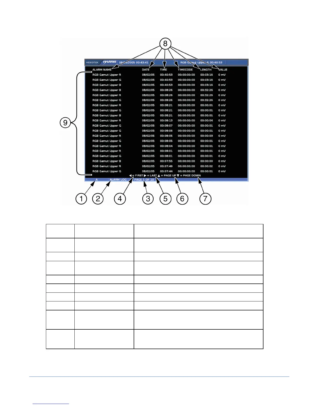
Figure 3-48. Alarm Log Diagram
Table 3-37. Description of Alarm Log Display Diagram
Field
Identifier
Field Information Nomenclature
1 Input Displays the user-configurable source IDs for the input and
routers.
2 Display Label Displayed as ALARM LOG
3 Page Information Displayed as PAGE X of Y, where X is the selected page
and Y is the total number of pages
4 Paging information Displays ◄ = FIRST page
5 Paging information Displays ► = LAST page
6 Paging information Displays ▲ = PAGE UP
7 Paging information Displays ▼ = PAGE DOWN
8 Column Labels Displays the labels # (for the number in the alarm list),
ALARM NAME, DATE, TIME, TIMECODELENGTH
(Duration), and PEAK VALUE*
9 Alarm List Displays the list of alarms from the most recent alarm to the
last recorded alarm (a maximum of 200 alarms can be
logged)
*NOTE: Certain alarm parameters do not have a level measurement that can report a peak
value. This is indicated when NO RPV (No Report Peak Value) appears in the PEAK VALUE
column. If A
3
-OPT2 is installed, all audio alarms will report NO RPV.