General Operation
32 TVM Series Installation and Operation Handbook
Copyright © 2008, Harris Corporation
Table 3-5. Video Formats and Critical Amplitude Limits
Video Format Critical Amplitude Limits
High Definition and Standard Definition
0.6125 V = upper 75% chroma limit
0.525 V = 75% luminance limit
0.350 V = 50% point; black for color difference
channels
0.0875 V = lower 75% chroma limit
Standard Definition 525 as Composite (NTSC) 7.5 IRE – black level
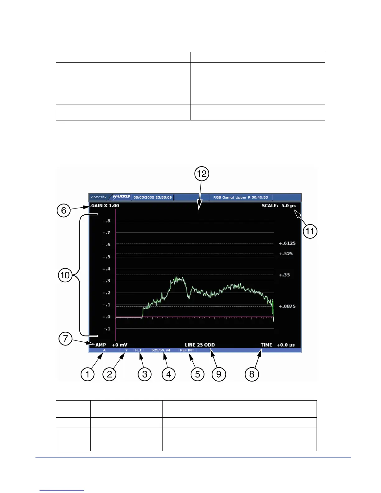
A waveform display is shown in Figure 3-6 and described in Table 3-6. The figure
shows the location for the various waveform display fields.
Figure 3-6. Waveform Display Diagram
Table 3-6. Description of Waveform Display Diagram
Field
Identifier
Field information Nomenclature
1 Input Displays user-configurable source IDs for input and routers
2 Format Displayed as YC
B
C
R
, RGB, YRGB, or Composite
(CMPST); this can be selected in the HD FORMAT or SD
FORMAT submenu of the WFM Pane menu