General Operation
50 TVM Series Installation and Operation Handbook
Copyright © 2008, Harris Corporation
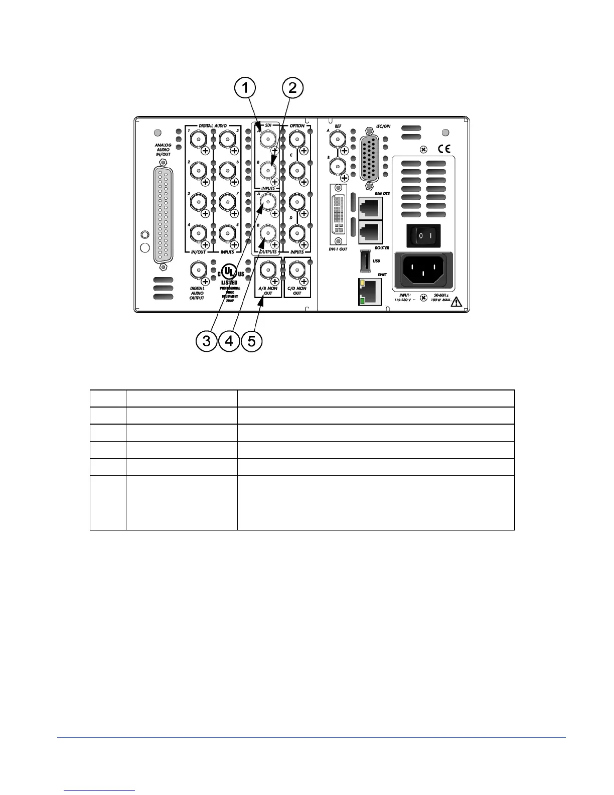
Figure 3-20. TVM-VTM-JEM Option Back Panel Connectors
Table 3-15. Description of TVM-VTM-JEM Option Back Panel Connectors
Key Label Description
1 A (IN) Female BNC HD-SDI or SD-SDI input connector
2 B (IN) Female BNC HD-SDI or SD-SDI input connector
3 A (OUT) Female BNC looping HD-SDI or SD-SDI output connector
4 B (OUT) Female BNC looping HD-SDI or SD-SDI output connector
5 A/B MON OUT Female BNC connector for monitoring of the selected A or B input
If both digital A + B inputs are selected, the output is input A (this
output is a source monitor only and does not include the
waveform, vector, audio, or alarm on-screen information)
NOTE: This option is only available for Inputs A and B only. Only one Eye Pattern and one
Jitter screen can be displayed at a time.
• TVM-40 displays Eye waveform or jitter/spectrum waveform in one or two
separate panes.
• TVM-10 displays Eye waveform or jitter/spectrum waveform in one pane at a time.
The Eye Pattern display is created by sampling the serial digital signal with the
recovered serial clock. The Eye Pattern display is used to measure signal amplitude,
jitter, rise time, and other irregularities. Measured parameters are shown a the top of
the EYE display, or they can be manually measured by setting the cursors on the
transition limits of the display and reading the offset in picoseconds (ps) for HD or
nanoseconds (ns) for SD. The amount of jitter can also be estimated from the bar
display above the Eye Pattern display. Amplitude is similarly measured using cursors.