Installation
16 TVM Series Installation and Operation Handbook
Copyright © 2008, Harris Corporation
Connecting the TVM
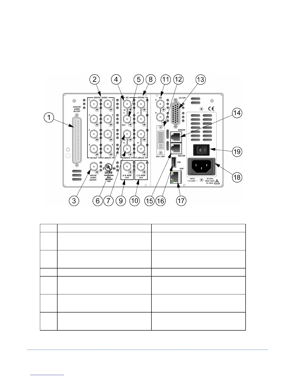
The back panel connectors are illustrated in Figure 2-2, and the function of each
connector is described in Table 2-2.
Figure 2-2. TVM Back Panel Connectors
Table 2-2. Description of Back Panel Connectors
Key Label Description
1 ANALOG AUDIO IN/OUT Optional 37-pin, D-sub, male connector; the
supplied breakout board can be used for
solderless connections*
2 DIGITAL AUDIO IN/OUT
1, 2, 3, 4 (IN/OUT),
5, 6, 7, 8 (IN ONLY)
Optional female BNC connectors for AES/EBU
and Dolby Digital audio input
3 DIGITAL AUDIO OUTPUT Female BNC connector for Dolby audio output
4, 5 SDI INPUT A Female BNC looping HD or SD SDI input
connector (termination required for passive
loop-thru inputs)
6, 7 SDI INPUT B Female BNC looping HD or SD SDI input
connector (termination required for passive
loop-thru inputs)
8 OPTION C, D (OPTION) Female BNC connectors for
optional inputs; holes are plugged if option is
not installed