General Operation
TVM Series Installation and Operation Handbook 73
Copyright © 2008, Harris Corporation
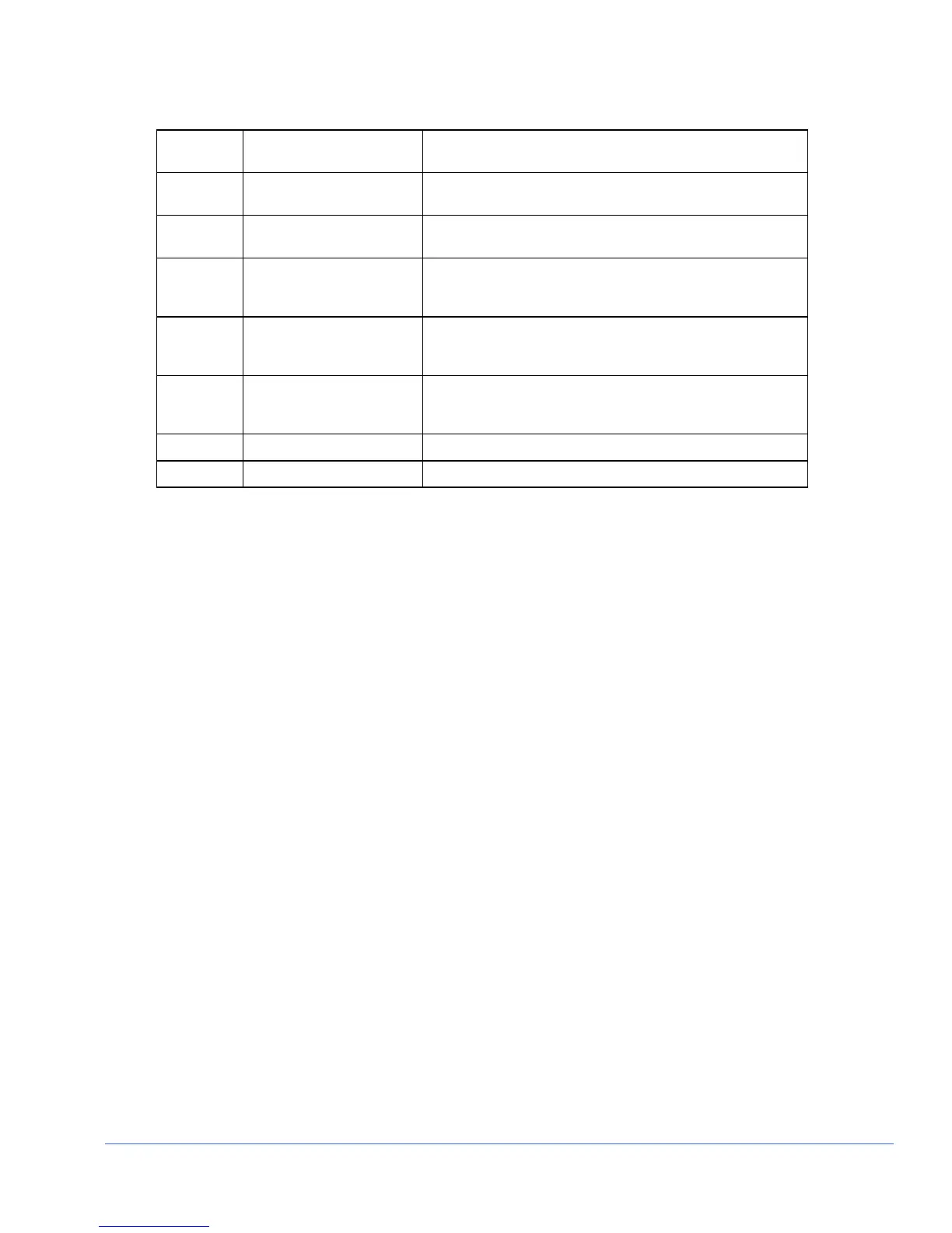
Table 3-27. Description of Gamut Display Diagram
Field
Identifier
Field Information Nomenclature
7 Line select information Line select is shown as Line and the number with the ODD
or EVEN field (when applicable)
8 Luma alarm limit Displays Luma when Composite is selected. This field is
blank when RGB is selected
9 Upper luma alarm limit
(Composite only)
Displayed as Upper = xxx yyl xxx is the Luma upper
threshold setting, and yy is determined by the format (IRE
for NTSC and Units or mV for PAL)
10 Lower luma alarm limit
(Composite only)
Displayed as Lower = xxx yy; xxx is the Luma lower
threshold setting, and yy is determined by the format (IRE
for NTSC and Units or mV for PAL)
11 Zoom
• Zoom (when enabled)
• Blank when disabled
• Press the ZOOM button to cycle through Zoom modes
12 Luma/Mono bar graticule Shows the Luma/Mono bar graticule
13 Gamut Graticule Composite or RGB Gamut graticule
Composite Gamut
The graticule for the composite gamut vector, as shown in Figure 3-41 and described
in Table 3-28, is two concentric circles with other identifiers. When setting the upper
and lower limits, the upper and lower gamut rings represent the values set from the
threshold values of the appropriate format. Set the 525 or 625 (check format) threshold
in the VIDEO ALARMS DIGITAL > DIGITAL GAMUT > PEAK GAMUT
(UPPER/LOWER) menu to move the gamut rings, or LUMA GAMUT
(UPPER/LOWER) > THRESHOLD 525/625 menu to move the luma bar limits. The
outer circle (the upper gamut alarm limit) represents the highest allowable amplitude in
standard composite units (i.e., IRE for NTSC and units for PAL). The inner circle (the
lower gamut alarm limit) represents the lowest allowable amplitude. The rings turn red
when the alarm is enabled and the values exceed the threshold setting.
The other identifiers are radials that extend at the angle of the designated color. These
six lines follow the same displacement as the vector display. Note that since the PAL
display is derived solely from component information, there are not two phases for
PAL signals. The +V phase is used (making the vectors look similar to NTSC).
NOTE: There is an alarm persistence of two seconds associated with any alarm indication.
After an alarm has cleared, two seconds will pass before the gamut alarm indicator returns to
normal.