General Operation
TVM Series Installation and Operation Handbook 61
Copyright © 2008, Harris Corporation
Utilizing the Vector Display
Pressing the VECT button accesses the Vector display for the selected pane. A vector
display is shown in Figure 3-28 and described in Table 3-23. This illustrates the
general location for the various vector fields.
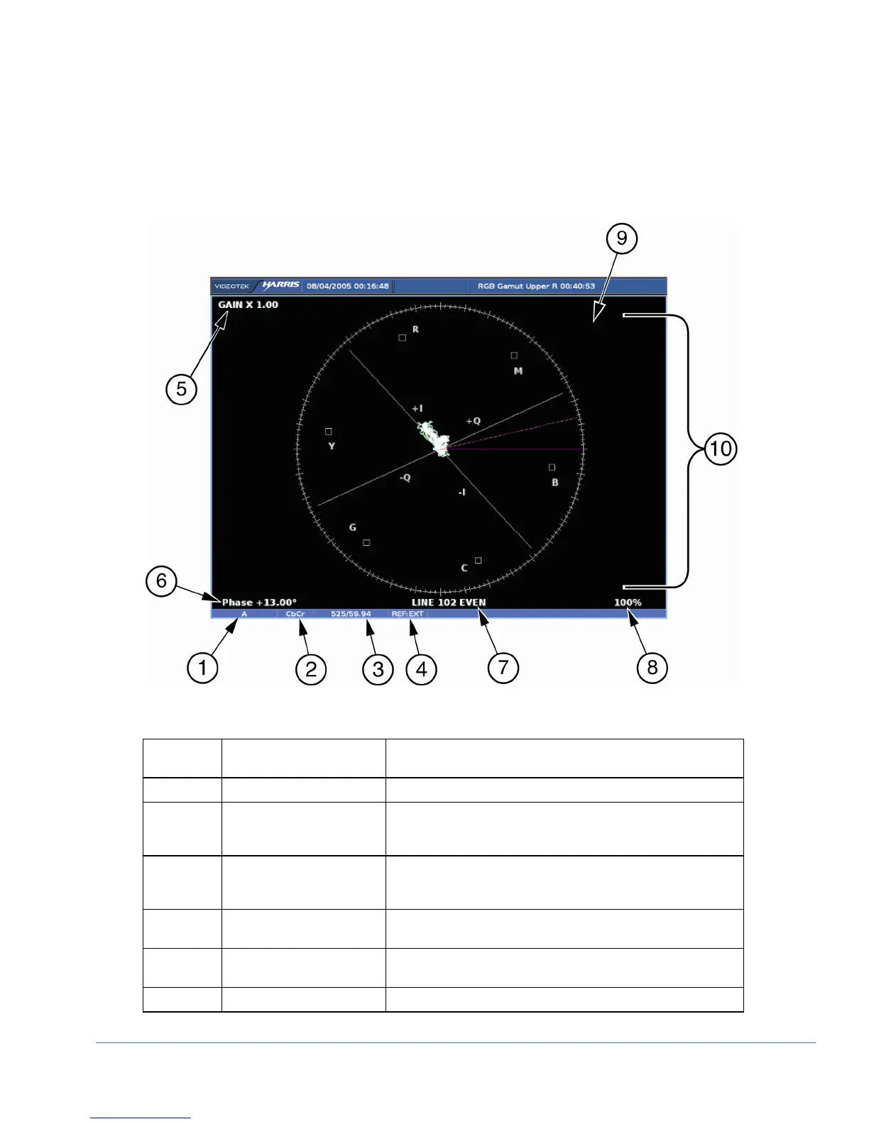
Figure 3-28. Vector Display Diagram
Table 3-23. Description of Vector Display Diagram
Field
Identifier
Field Information Nomenclature
1 Input Displays user-configurable source IDs for input and routers
2 Format Displayed as Composite and C
B
C
R
; this can be selected in
the HD FORMAT or SD FORMAT submenu of the VECTOR
Pane menu
3 Standard Displays the Line Rate/Frame Rate [1080i/59.94]; this is
selected in the VIDEO FORMAT > VIDEO A THRU D
CONFIGURE menu
4 Reference Displays the reference as INT, EXT; this is toggled by
pressing the EXT button
5 Gain Displays gain where Gain is 1.00, 2.50, 5.00, or 15.00; this
is changed by pressing the STEP or VAR button
6 Phase cursor readout Displays Phase cursor as PHASE and number in degrees