General Operation
74 TVM Series Installation and Operation Handbook
Copyright © 2008, Harris Corporation
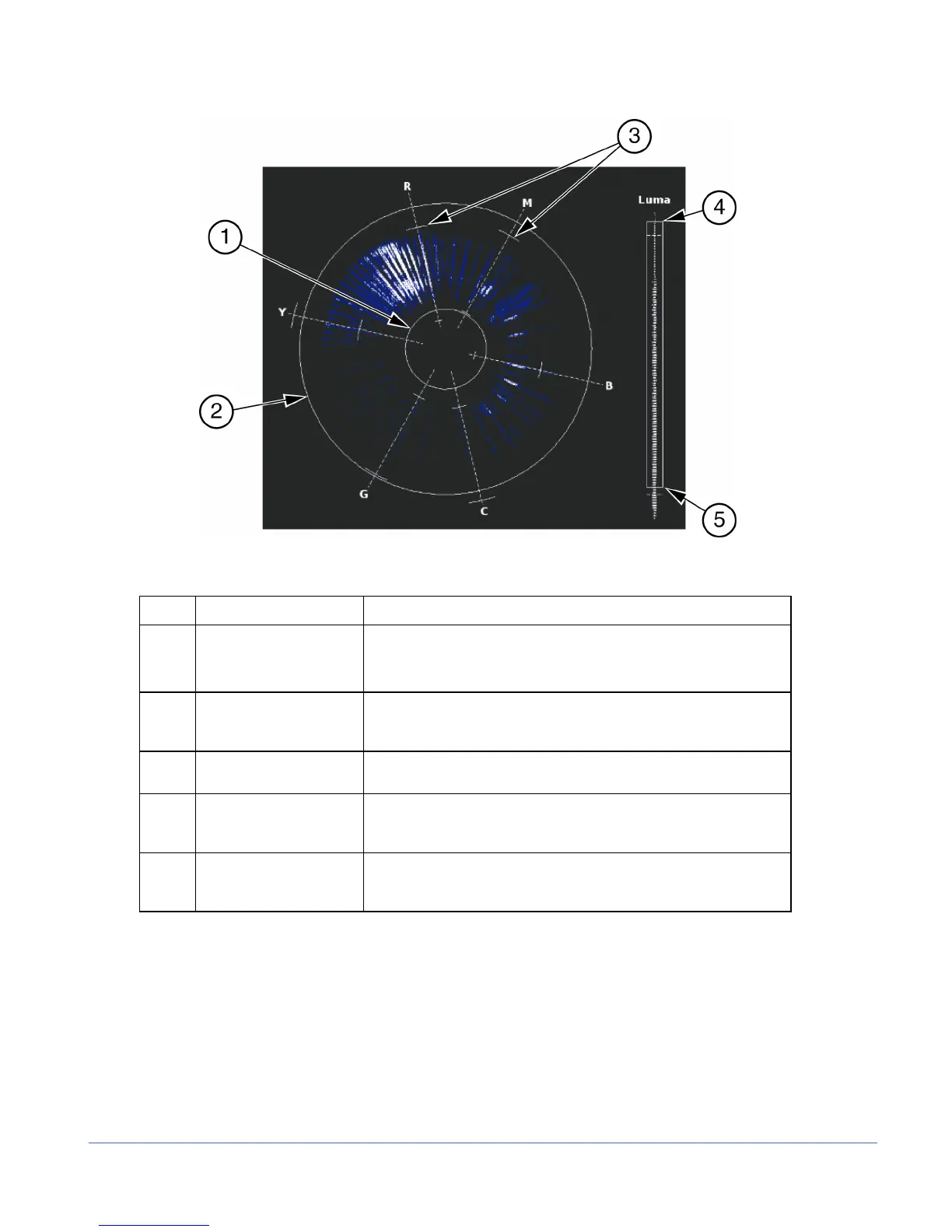
Figure 3-41. Composite Gamut Vector Display Graticule Markings
Table 3-28. Description of Composite Gamut Indicators
Key Indicator Description
1 Lower Gamut Ring The lower gamut ring indicates the Gamut alarm Peak Lower limit.
When the Gamut alarm is enabled and the Peak Lower limit is
exceeded, the lower gamut ring turns red.
2 Upper Gamut Ring The upper gamut ring indicates the Gamut alarm Peak Upper
limit. When the Gamut alarm Peak Upper limit is exceeded, the
upper gamut ring turns red.
3 Vector Excursion Mark The excursion marks help to visualize the minimum/maximum
value of 100% color bars.
4 Luma Upper Limit Line The Luma Upper Limit Line indicates the Gamut alarm Luma Upper limit.
When the Gamut alarm is enabled, and the Luma Upper limit is exceeded,
the luma upper limit line and LUMA turn red.
5 Luma Lower Limit Line The Luma Lower Limit Line indicates the Gamut alarm Luma Lower limit.
When the Gamut alarm is enabled, and the Luma lower limit is exceeded,
the Luma Lower Limit line and LUMA turn red.
RGB Gamut Display
When setting the upper and lower limits, the upper and lower gamut rings represent the
threshold values. Set the threshold in the VIDEO ALARMS DIGITAL > DIGITAL
GAMUT > RGB (UPPER/LOWER) > THRESHOLD menu to move to gamut rings.
The RGB Gamut Display, shown in Figure 3-42 and described in Table 3-29, is
similar to the Composite Gamut Display. The RGB Gamut vector displays video
amplitudes (which are in mV) in a polar format to represent color information. The
rings turn red when the alarm is enabled and the values exceed the threshold setting.