General Operation
TVM Series Installation and Operation Handbook 75
Copyright © 2008, Harris Corporation
Each R, G, and B pixel is plotted using amplitude and phase. The amplitude is derived
from the R, G, B component. The phase is derived from the C
B
C
R
information of the
digital signal. The pixels can be plotted as a single color or as each component color
(see the Gamut Setup menu in Section 4). Unlike the composite Gamut vector, which
plots two points per pixel, the RGB Gamut vector plots three points. Also, signals with
no color content are displayed on a separate bar graph labeled Mono.
The RGB graticule is nearly identical to the composite graticule. The only differences
are:
• Amplitudes are displayed in mV rather than IRE or UNITS.
• The radials representing color vectors are 60° apart since they are displayed in a
component color space.
• Mono bar graph is for monochrome.
NOTE: There is an alarm persistence of two seconds associated with any alarm indication.
After an alarm has cleared, two seconds will pass before the gamut indicator returns to normal.
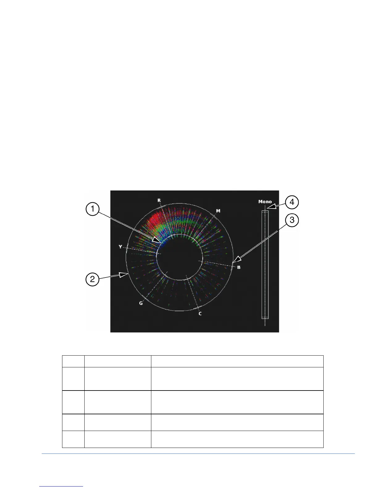
Figure 3-42. Component Gamut Vector Display Graticule Markings
Table 3-29. Description of RGB Gamut Indicators
Key Indicator Description
1 Lower Gamut Ring The lower gamut ring indicates the RGB Gamut alarm Lower limit.
When the RGB Gamut alarm is enabled and the Lower limit is
exceeded, the lower gamut ring turns red.
2 Upper Gamut Ring The upper gamut ring indicates the RGB Gamut alarm Upper limit.
When the RGB Gamut alarm is enabled, and the Upper limit is
exceeded, the upper gamut ring turns red.
3 Vector Excursion Mark The excursion marks help to visualize the minimum/maximum
values of 100% color bars.
4 Mono Mono indicates the monochrome of the RGB signal. There is no
alarm associated with Mono.