General Operation
72 TVM Series Installation and Operation Handbook
Copyright © 2008, Harris Corporation
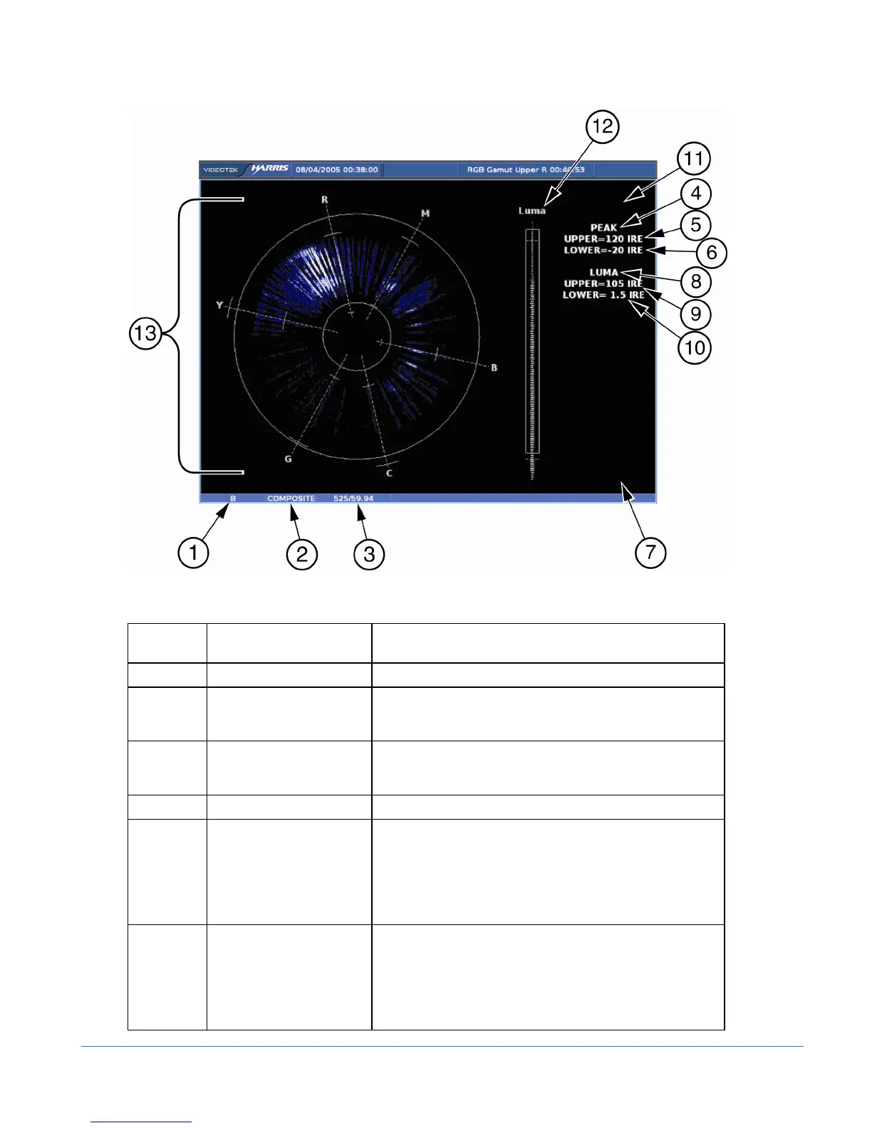
Figure 3-40. Gamut Display Diagram
Table 3-27. Description of Gamut Display Diagram
Field
Identifier
Field Information Nomenclature
1 Input Displays user-configurable source IDs for input and routers
2 Format Displayed as Composite and RGB; this can be selected in
the HD FORMAT or SD FORMAT submenu of the GAMUT
Pane menu
3 Standard Displays the Line Rate/Frame Rate [1080i/59.94]; this is
selected in the VIDEO FORMAT > VIDEO A THRU D
CONFIGURE menu
4 Chroma alarm limits Displayed as RGB (for RGB) and PEAK (for Composite)
5 Upper chroma alarm limit Displayed as Upper = xxx yy
• For RGB xxx is the RGB Gamut upper threshold
setting and yy is shown as mV
• For Composite, xxx is the Peak upper threshold
setting. In Composite, yy is determined by the format
(IRE for NTSC and Units or mV for PAL)
6 Lower chroma alarm limit Displayed as Lower = xxx yy
• For RGB xxx is the s the RGB Gamut lower threshold
setting, and yy as units
• For Composite, xxx is the Peak lower threshold
setting. In Composite, yy is determined by the format
(IRE for NTSC and Units for PAL)