General Operation
88 TVM Series Installation and Operation Handbook
Copyright © 2008, Harris Corporation
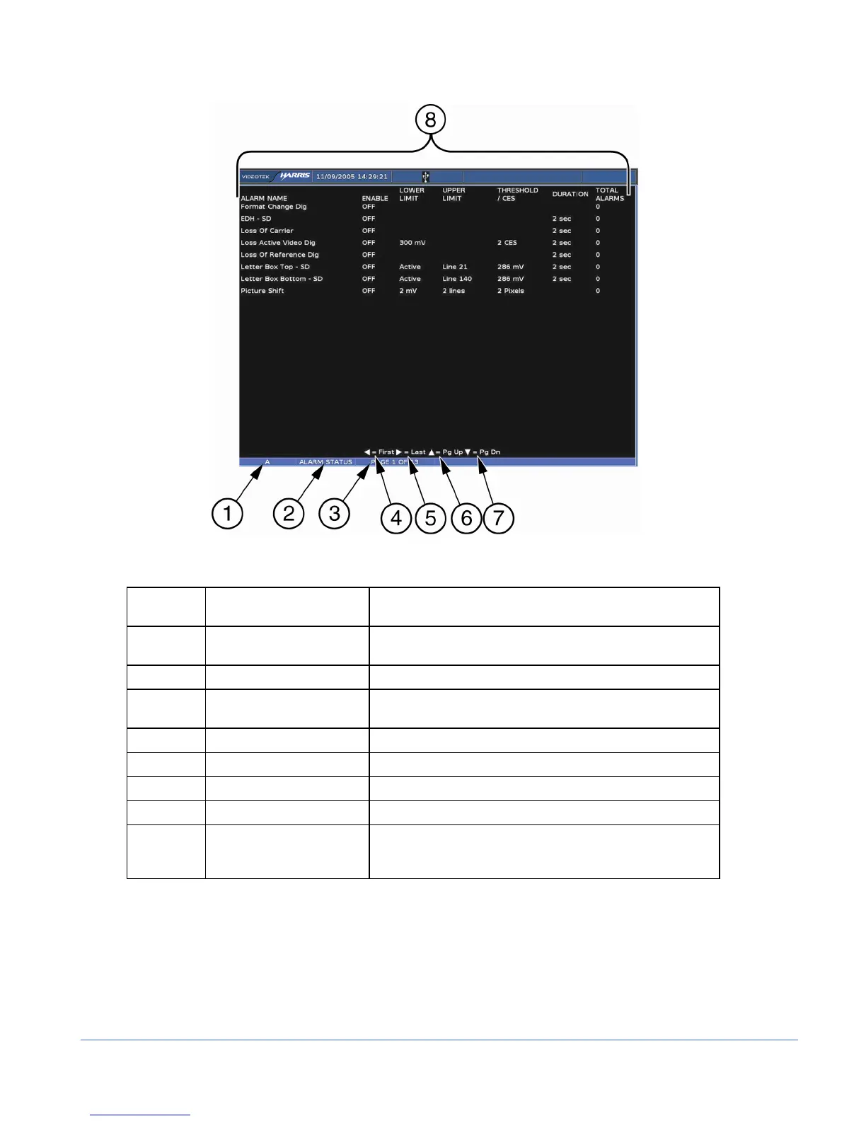
Figure 3-49. Alarm Status Display Diagram
Table 3-38. Description of Alarm Status Display Diagram
Field
Identifier
Field Information Nomenclature
1 Input Displays the user-configurable source IDs for the input and
routers.
2 Display Label Displayed as ALARM STATUS
3 Page Information Displayed as PAGE X of Y, where X is the selected page
and Y is the total number of pages.
4 Paging information Displays ◄ = FIRST page.
5 Paging information Displays ► = LAST page.
6 Paging information Displays ▲ = PAGE UP.
7 Paging information Displays ▼ = PAGE DOWN.
8 Column Labels Displays the columns ALARM NAME, ENABLE, LOWER
LIMIT, UPPER LIMIT, THRESHOLD/CES, DURATION,
and TOTAL ALARMS.
The alarm status screen contains alarm name text that can appear in a colored state. The
colored states are:
• White: indicates alarm is not enabled.
• Green: indicates alarm is enabled and not exceeding alarm limits.
• Red: indicates the alarm is enabled and exceeding an alarm limits.
There is a two-second persistence for any Alarm Name color change.