General Operation
120 TVM Series Installation and Operation Handbook
Copyright © 2008, Harris Corporation
“cosited” Y sample) for the first pixel of the group and combined with the second Y
sample (Y’, or Y prime) for the second pixel.
The Pixel Cursor and the zoomed picture elements are displayed next to the data. The
target area within the Pixel Cursor reflects the Pixel Group Display menu selection 2H,
8H, or 2H x 4V. When selecting Data Analyzer, the pixel cursor appears on the picture
pane. The Pixel cursor shows the location of the data displayed in the Data zoom pane.
Look at the Picture Zoom display for the precise location of the Data display cursor.
The Pixel Cursor is described in Pixel Cursor on page 121.
Referring to item 6 in Figure 3-66, the first pixel will be formed from the samples
1440, 1441, and 1442. The color information for this pixel comes from C
B
and C
R
, or
samples 1440 and 1442. Sample 1441 is the unique Y sample.
When Line Select is enabled, the cursor on the picture can be moved up and down with
the CURVED ARROW Knob. Pressing the UP and DOWN navigation buttons or
turning the HORIZONTAL knob moves the cursor left and right.
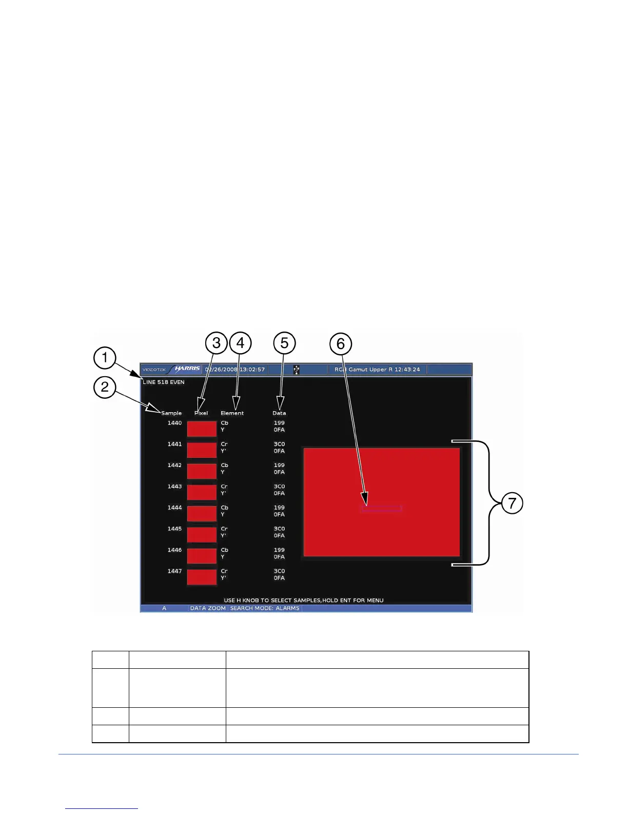
A sample Data Mode display is shown in Figure 3-66 and described in Table 3-58.
Figure 3-66. Data Mode Display (HD-SDI and SD SDI Only)
Table 3-58. Description of Data Mode Display (SD-SDI and HD SDI Only)
Key Indicator Description
1 LINE Indicator that shows the line number of the picture along with the Even
(E) and/or Odd (O) line selection; line number corresponds to the
cursor on the picture
2 SAMPLE Indicates the selected pixel samples inside the pixel cursor.
3 PIXEL Complete information for two pixels