3.2.6 Configure the CAN network
Depending on the machine type the layout of the CAN network will be different.
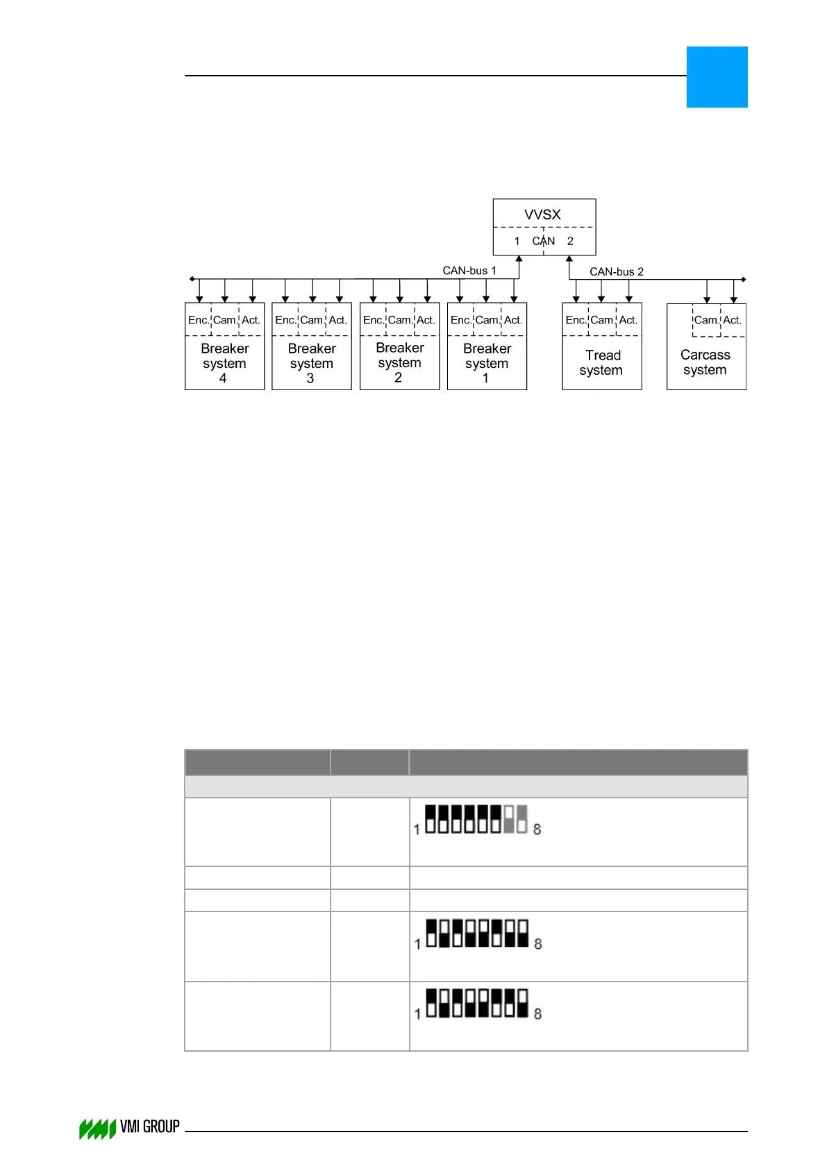
The illustration shows the maximum configuration.
The CAN AC2 PCI card supports two CAN busses:
● CAN 1: 9‑pole D‑sub connector for breaker conveyors.
● CAN 2: 9‑pole D‑sub connector for carcass and tread conveyors.
The CAN network consists of the following components:
● VVSX controller.
● Erhardt + Leimer cameras (OL80XX or OL82XX where XX indicates the lens type)
● Erhardt + Leimer actuators (RK4004)
● Erhardt + Leimer digital I/O (ZC4002 + LK4002)
● Beckhoff BK5120 CANopen terminal with one or two encoder counters of type
● KL5101 (incremental encoder interface RS485 ±12V DC), or
● KL5111 (incremental encoder interface 24V DC).
The encoders of the breaker systems are all connected to one Beckhoff BK5120 module.
The cameras and actuators are directly connected to the CAN‑bus.
Each system can have 1 or 2 cameras directly connected to the CAN‑bus.
3.2.6.1 Addresses of all devices in the CAN network
Devices
Address
1
Address setting (dipswitch)
2
CAN channel 1
Beckhoff BK5120 3.F
How to set the address of Beckhoff BK5120
Camera Breaker 1+3 0.1 How to set the address of the camera
Camera Breaker 2+4 4.1 How to set the address of the camera
Actuator Breaker 1 2.5
How to set the address of actuator RK4004
Actuator Breaker 2 6.5
How to set the address of actuator RK4004
INSTALLATION AND CONFIGURATION
Configuration
3
THINKING FORWARD
VMI Vision System VVS (OL82) VVSX 13.0.12.0, VVSU 3.0.6 / 4 / 2016-07-11 / pd#175592
3-15