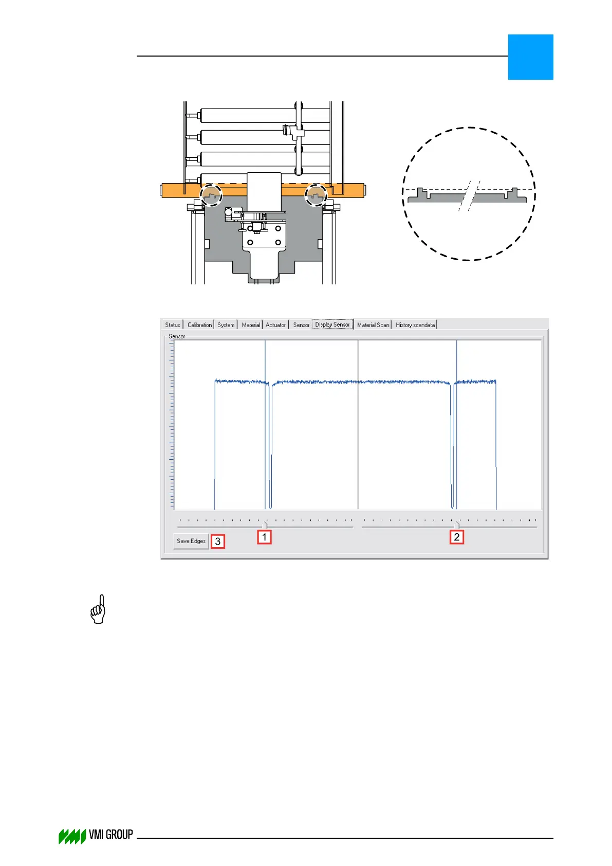
9. Place the calibration template on the conveyor belt as follows:
In the DISPLAY SENSOR tab, the calibration template protrusions are visible as
spikes.
10.
Position the left [1] and right [2] rulers of the camera image just outside of the spikes.
NOTICE
Make sure that you move the rulers always a bit before you click SAVE EDGES.
Otherwise, it is possible that the edge positions are not sent to the camera.
11. Click SAVE EDGES[3] to send the new Region Of Interest to the camera.
12. Remove the calibration template.
13. Mount the lens protection cover [1].
14. Enable the white balance:
● In VVSU, go to tab SENSOR.
● Change the value of Start Service to 10 and pres ENTER.
● Click TRANSMIT to send the values to VVSX.
After a few seconds the value returns to 0.
ALIGNMENTS, ADJUSTMENTS AND CALIBRATIONS
VVS Breaker
5
THINKING FORWARD
VMI Vision System VVS (OL82) VVSX 13.0.12.0, VVSU 3.0.6 / 4 / 2016-07-11 / pd#175592
5-12