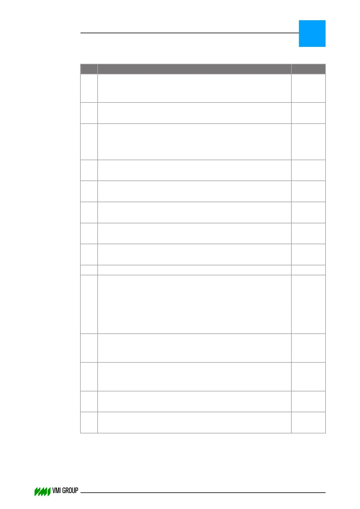
6.4.2 Sensor errors (word 1)
Bit Sensor error Remarks
0 Hardware failure sensor 1
Bit directly copied from the CAN message from the camera.
This bit indicates an internal error in the camera.
A
1 Sensor 1 not calibrated
Set if physical camera 1 not (properly) calibrated.
A
2 Low light level sensor 1
Low light level for physical camera 1. Open aperture or increase the
light intensity.
Camera can be misaligned.
A, B
3 Material under sensor 1 after Homing
Function unclear, harm is already done.
A
4 Hardware failure sensor 2
Same as bit 0 for optional second camera.
A, C
5 Sensor 2 not calibrated
Same as bit 1 for optional second camera.
A, C
6 Low light level sensor 2
Same as bit 2 for optional second camera.
A, B, C
7 Material under sensor 2 after Homing
Same as bit 3 for optional second camera.
A, C
8 No material under sensors D
9 No TE signal received
Centering is completed, but during the transition from body to trailing
edge there was no signal from the PLC that the switch should be
made.
VVS has decided on it's own to switch to trailing edge centering.
This may lead to a 'dent' in the breaker area around the beginning of
the trailing edge.
D, E
10 Material to wide
This bit is set when the moving average of 20 samples exceeds the
tolerance.
D
11 Material to narrow
This bit is set when the moving average of 20 samples exceeds the
tolerance.
D
12 Sensor 1 overexposed
Refer to remarks.
A, B
13 Sensor 2 overexposed
Refer to remarks.
A, B, C
PARAMETERS
Status buffer
6
THINKING FORWARD
VMI Vision System VVS (OL82) VVSX 13.0.12.0, VVSU 3.0.6 / 4 / 2016-07-11 / pd#175592
6-18