Page: 1-28
WALKER MANUFACTURING COMPANY
July 2006
SERVICE INSTRUCTIONS
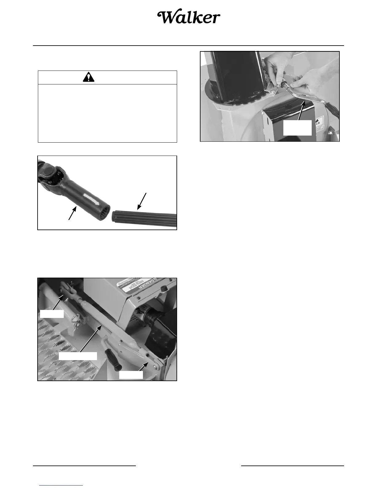
9. Attach the driveline quick lock coupler to the tractor
PTO.
Connect Driveline Coupler to Tractor PTO
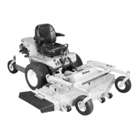
10. Attach the parallel bar to the female hitch and the
implement adaptor using the two clevises and
spring clips.
Attach Parallel Bar to Female Hitch
11. Insert the rotation handle into the rotation worm.
Align the holes and lock in place with a 1/4 x 1 in.
socket head cap screw and nylon locknut.
12. Install the plastic handle grip on the chute rotation
handle.
Insert Rotation Handle into Rotation Worm
13. To install the optional tire chains:
a. Remove the tractor wheels.
b. Attach the tire chains to the wheels.
c. Place the wheel spacer plates on the lug
bolts. The wheel spacer plates provide clear-
ance for the chains between the tires and the
tractor body.
d. Place the wheels back on the tractor.
e. Reinstall and tighten the lug bolts.
14. For GHS (Grass Handling System) equipped
Walker tractors, install a blower intake cover in the
blower intake tube. The cover “unloads” the blower
and seals the intake to effectively eliminate power
loss and noise when the blower is not being used.
Refer to GHS Blower Intake Cover illustration for
ROTARY BROOM in this section.
15. For stability of the tractor when transporting with
the snowblower in raised position, approximately
80 lb (36 kg) of counterweight should be installed
on the tail of the tractor. Optional tail weights for
the various tractor models are available from your
Walker dealer or a sandbag or similar weight may
be used.
WARNING
This shaft turns at high RPM. If the collar
is not locked to the shaft at the tractor
end, or if the yoke at the blower end is not
secured properly, the drive shaft can fly
loose with great force, capable of causing
serious injury or death.
Driveline Coupler
Tractor PTO
Clevis
Clevis
Parallel Bar
Rotation
Handle