6 Introduction
• Hold output switch - Transmits a signal from the 600 controller to an external
device when the controller receives a:
– Stop Flow signal
– Hold screen key signal
– Pressure limit error
– Pump flow rate error
Event Switches/Aux +12 V
Four TTL-compatible connectors (S1 through S4) on the controller rear panel:
• Control column-switching valves, fraction collectors, or similar external devices
• Operate manually or automatically through the 600 controller screens
• Function in conjunction with a built-in auxiliary power supply terminal
(Aux +12 V) for devices that require an external power source
1.2.2 Waters 600E Pump
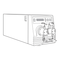
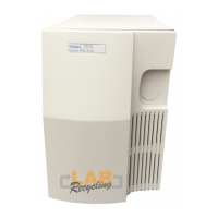
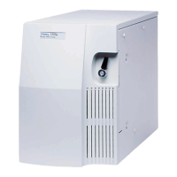
The Waters 600E pump (Figure 1-4 and Figure 1-5) contains the components required to
blend and deliver eluents from the reservoir bottles to the injector.
The Waters 600E pump features:
• Four-eluent blending (Auto•Blend)
• Manual, variable-volume injector (optional)
• Vent valve (optional)



 To Next Page