2
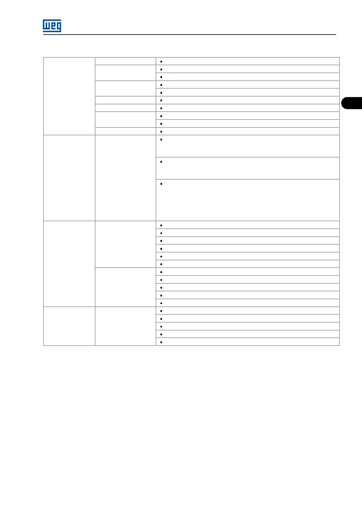
GENERAL INFORMATION
CONTROL
Microprocessor 32 bits.
Control method
Sinusoidal PWM with Space Vector Modulation (SVM)
Sinusoidal PWM with Optimized Pulse Patterns (OPP) Digital.
Control types
Scalar (Imposed Voltage - V/F)
Vector (encoder and sensorless)
Switching High voltage IGBT transistor IGBT (HV - IGBT)
Frequency range 0 a 120 Hz
Allowed overload
150 % during 60 seconds, every 10 minutes (1.5 x Inom. - HD).
115 % during 60 seconds, every 10 minutes (1.15 x Inom. - ND).
Efficiency Higher 98,5 %
PERFORMANCE Speed control
V/F
Regulation: 1 % of the nominal speed with slip compensation.
Resolution: 1 rpm (keypad reference).
Sensorless
Regulation: 0,5 % of the nominal speed.
Speed variation range: 1:100.
With Encoder (using EBA or EBB board).
Regulation:
±0,01 % of the nominal speed with a 14-bit analog input (EBA).
±0,01 % of the nominal speed with digital reference (keypad, Serial, Fieldbus, Elec-
tronic Potentiometer, Multispeed).
±0,1 % of nominal speed with 10-bit analog input (CC9).
INPUTS OUTPUTS
Analogical
2 programmable differential inputs (10 bits): 0 to 10 V, 0 to 20 mA or 4 to 20 mA.
1 programmable bipolar input (14 bits): -10 to +10 V, 0 to 20 mA or 4 to 20 mA.
1 programmable isolated input (10 bits): 0 to 10 V, 0 to 20 mA or 4 to 20 mA.
2 programmable outputs (11 bits): 0 to 10 V.
2 bipolar programmable outputs (14 bits): (-10 to +10) V.
2 programmable isolated outputs (11 bits): 0 to 20 mA or 4 to 20 mA.
Digital Analog Relay
Transistor
8 programmable isolated inputs: 24 Vdc.
1 programmable isolated input: 24 Vdc.
1 programmable isolated input: 24 Vdc (for motor PTC thermistor).
5 programmable outputs, contacts NO/NC: 240 Vac, 1 A.
2 programmable isolated open collector outputs: 24 Vdc, 50 mA.
COMMUNICATION
Serial Interface Fieldbus
Networks
RS-232 (point to point).
RS-485, isolated, via EBA or EBB board (multipoint up to 30 inverters).
Modbus RTU (incorporated software) via RS-485 serial interface.
Profibus DP or DeviceNet via additional KFB kits.
Ethernet or Profinet IO via additional KFB.
MVW01 | 2-3