5
MVW01C (COMPACT)
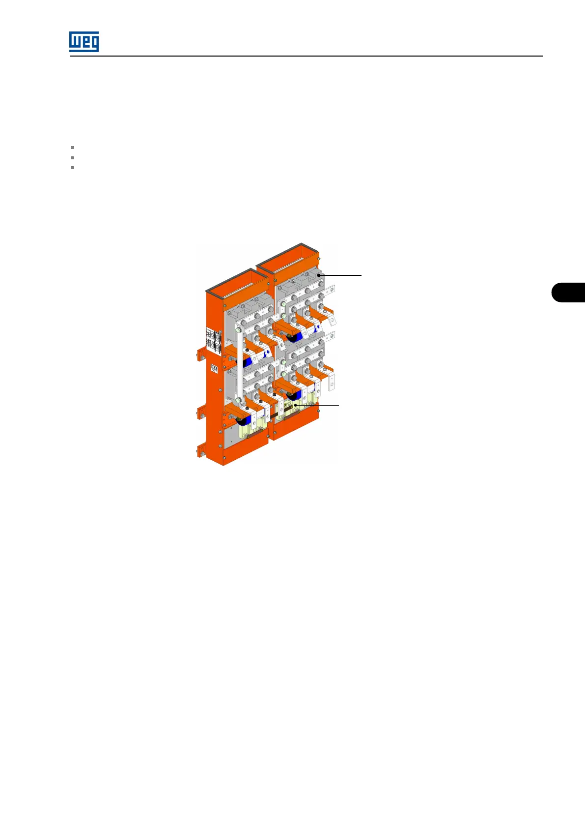
Input rectifier
The medium voltage cables for the input rectifier (A1) supply come from the input transformer secondary windings. The transformer configuration
and the number of cables depend on the rectifier number of pulses:
6 cables for the 12 pulse configuration.
9 cables for the 18 pulse configuration.
12 cables for the 24 pulse configuration.
Considering the standard rectifier version (18 pulses) the secondary winding voltage depends on the motor nominal voltage, being 1.5 kV for
motors with 4160 V rated voltage and 1.2 kV for motors with 3300 V rated voltage. The 9 cables may be inserted through the bottom part of
the rectifier cabinet or through the top of the inverter cabinet, being connected directly to terminations in copper bars mounted on the module
(A1).
Diodes
Equalization resistors
Figure 5.3: MVW-01C 18-pulse rectifier
The rectifier is connected to the DC link located at the rear part of the MVW-01C panel, at the inverter compartment. The resistors for the DC
bus voltage balancing are mounted together with the rectifier. The DC bus supplies the voltage for the three inverter power arms.
MVW01 | 5-3