10
INSTALLATION, CONNECTION AND ENERGIZATION
Picture
Insertion Procedure
6
9. The power arm insertion procedure is complete.
✓
NOTE!
In order to extract the power arms follow the procedures described in the previous sections in reverse order.
Table 10.5: Procedure for the installation of power supply and fiber optic cables on the power arms
Picture
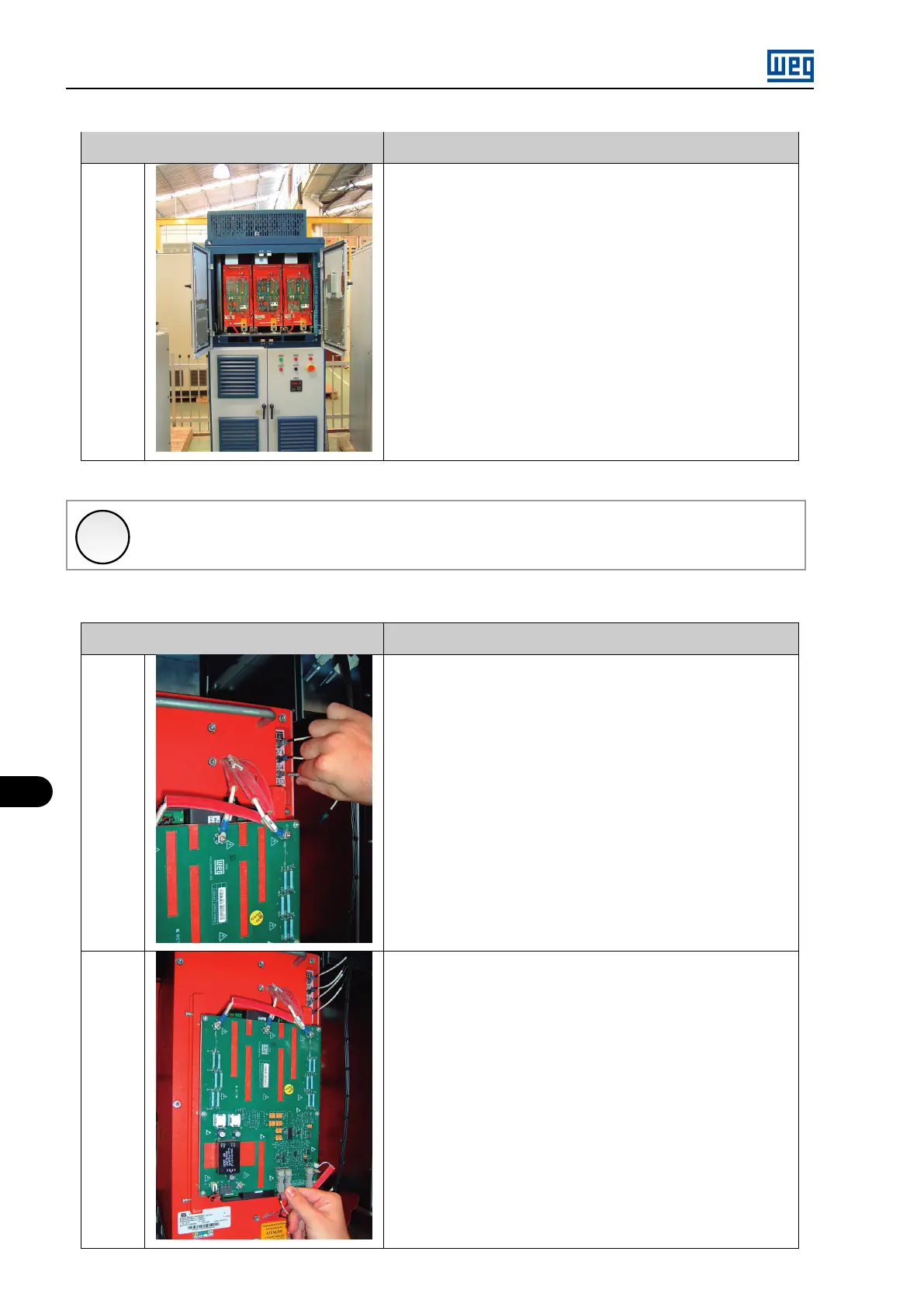
Connection Procedure
1
1. Connect the gate (GS1, GS2, GS3 and GS4) and status (VST1, VST2,
VST3 and VST4) fiber optic cables according to the picture 1.
2
2. In order to connect the ISOX fiber optic cables and the power supply
cable, it is necessary to remove the protective acrylic cover.
3. Connect the optic fibers OSA, OSB, and TEMP, and the power supply
cable XC1, according to the picture 2.
MVW01 | 10-12