10
INSTALLATION, CONNECTION AND ENERGIZATION
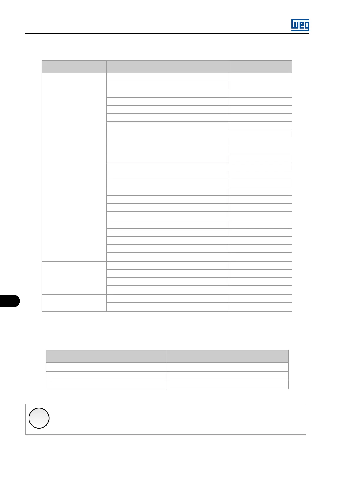
Table 10.6: Recommended power cables cross section (copper) [AWG]
Power Cables [mm²]:
U, V, W, VAS, VBS, VCS, VAD, VBD, VCD
Maximum Current [A]
Single Cable
10
71
16 96
25 126
35
157
50 189
70
241
95 292
120 337
150 384
185 438
240
514
Two Cables
2x50*
302
2x70*
386
2x95*
467
2x120*
539
2x150*
614
2x185*
701
2x240*
822
Three Cables
3x95*
613
3x120*
708
3x150*
806
3x185*
920
3x240*
1079
Four
4x120*
876
4x150*
998
4x185*
1139
4x240*
1336
Five
5x185*
1314
5x240*
1542
(*) It is recommended that the connection of parallel cables be made with auxiliary busbars.
Table 10.7: Recommended power cables cross section (copper)
Gauge of the Power Cables (S cross section) [mm²]
Minimun Gauge of the Grounding Cables (S cross
section) (PE) [mm²]
S ≤ 16
S
16 < S ≤ 35
16
35 < S S / 2
✓
NOTE!
The cable cross sections/gauges presented in the Table 10.7 on page 10-14 are only orientative.
In order to size the cables correctly the installation conditions, the applicable standards and regulations, and the maximum
allowed voltage drop must be considered.
MVW01 | 10-14