11
OPTIONAL ACCESSORIES AND BOARDS
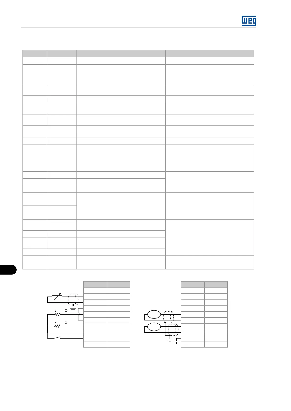
Table 11.6: Description of the XC4 connector (full EBA board)
Connector
Signal
Function (factory default) Specification
1
NC
- -
2
DI8
Input 1 for the motor thermistor - PTC1 (See
P0270)
Actuation: 3.9 kΩ
Release:1,6 k Ω
Minimum resistance: 100Ω
3
DGND (DI8)
Input 2 for motor thermistor - PTC 2 (See P0270) Referenced to DGND (DI8) through a 249 Ω re-
sistor
4
DGND
0 V reference of the 24 Vdc power supply Grounded via 249 Ω resistor
5
DO1
Transistor output 1: Not used Isolated, open collector, 24 Vdc, max: 50 mA, re-
quired load (Rc) 500 Ω
6
COM
Common point DI7 digital input and DO1 and DO2
digital outputs
-
7
DO2
Transistor output 2: Not used Isolated, open collector, 24 Vdc, max: 50 mA, re-
quired load (Rc) 500 Ω
8
24 Vdc
Power supply for digital inputs/outputs 24 Vdc ± 8% Isolated, Capacity: 90 mA
9
DI7
Isolated digital input: Not used
Minimum high level: 18 Vdc
Maximum low level: 3 Vdc
Maximum voltage: 30 Vdc
Input current: 11 mA @ 24 Vdc
10
SREF
Reference for RS-485
Isolated RS-485 serial
11
A-LINE
RS-485 A-LINE
12
B-LINE
RS-485 B-LINE
13
AI4 +
Analog input 4: Speed reference
Programmable differential (see P0243)
Resolution: 14 bits (0.006% of full scale)
14
AI4 -
Impedance: 40 kΩ (-10 to +10) V
500 Ω [(0 to 20) mA/(4 to 20) mA]
15
AGND
0 V reference for analog output (internally
grounded)
Resolution: 14 bits (0.006% of full scale)
Required load (Rc) 2 kΩ
16
AO3
Analog output 3: Speed
17
AGND
0 V reference for analog output (internally
grounded)
18
AO4
Analog output 4: Motor current
19
+V
External power supply for encoder repeater
output (XC8)
External power supply: 5 to 15 V
Consumption: 100 mA @ 5 V, excluding the
outputs
20
COM 1
Connector
Signal
Rc 500
Rc 500
1
2
3
4
5
6
7
8
9
10
rpm
A
Connector
Signal
11
12
13
14
15
16
17
18
19
20
NC
DI8
DGND (DI8)
DGND
DO1
COM
DO2
24 Vdc
DI7
SREF
A-LINE
B-LINE
AI4+
AI4-
AGND
AO3
AGND
AO4
+V
COM 1
Figure 11.5: Description of the XC4 connector (full EBA board)
ENCODER CONNECTION: refer to Section 11.3 INCREMENTAL ENCODER on page 11-14
INSTALLATION
The EBA board is installed directly on the MVC4 control board, secured with spacers and connected via terminal blocks XC11 (24 V) and XC3.
Mounting instructions:
MVW01 | 11-6