11
OPTIONAL ACCESSORIES AND BOARDS
1. De-energize the control rack;
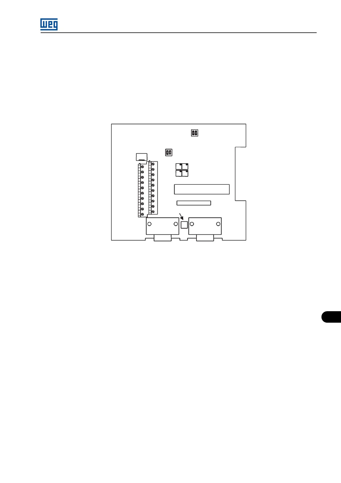
2. Configure the board via S2 and S3 DIP switches (refer to the Table 11.7 on page 11-8 );
3. Carefully insert XC3 connector (EBA) into the female connector XC3 on the MVC4 control board. Make sure that all pins fit in the XC3
connector;
4. Press on the EBA board (near to XC3) and on the left top edge until the complete insertion of the connector and the plastic spacer;
5. Secure the board to the 2 metallic spacers with the 2 provided bolts;
6. Plug the XC11 connector of the EBA board to the XC11 connector on the MVC4 control board.
Figure 11.6: Position of the adjustment elements - EBA board
MVW01 | 11-7