July 2019
4-30
Xerox® B205/B215 Multifunction Printer Service Manual
REP 4.9
Initial Release
Repairs / Adjustments
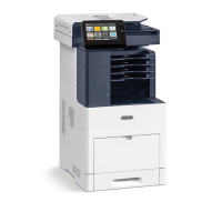
16. Remove the PWBs, Figure 9:
a. Disconnect the connectors, the ground wire, and the FFC cable on the HVPS PWB.
b. Remove six screws attaching the HVPS PWB.
c. Remove the four spring contacts from the high voltage contact guide.
d. Disconnect the connectors, remove six screws attaching the LVPS PWB, Remove
t
he LVPS PWB, then remove the insulation pad behind the LVPS PWB.
e. Remove six screws attaching the LVPS PWB, then remove the insulati
on pad behind
t
he LVPS PWB.
f. Disconnect the connectors, remove five screws attaching the Main PWB, t
hen
rem
ove the Main PWB.
Figure 9 PWB Removal
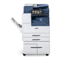
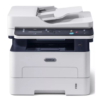
17. Remove two screws on the left-side, F
igure 10, two screws on the right-side, Figure 11,
t
hen remove the LSU Assembly.
Figure 10 LSU Left Side Screws
Figure 11 LSU Right Side Screws
 Loading...