July 2019
4-22
Xerox® B210 Service Manual
REP 4.9
Initial Release
Repairs - Adjustments
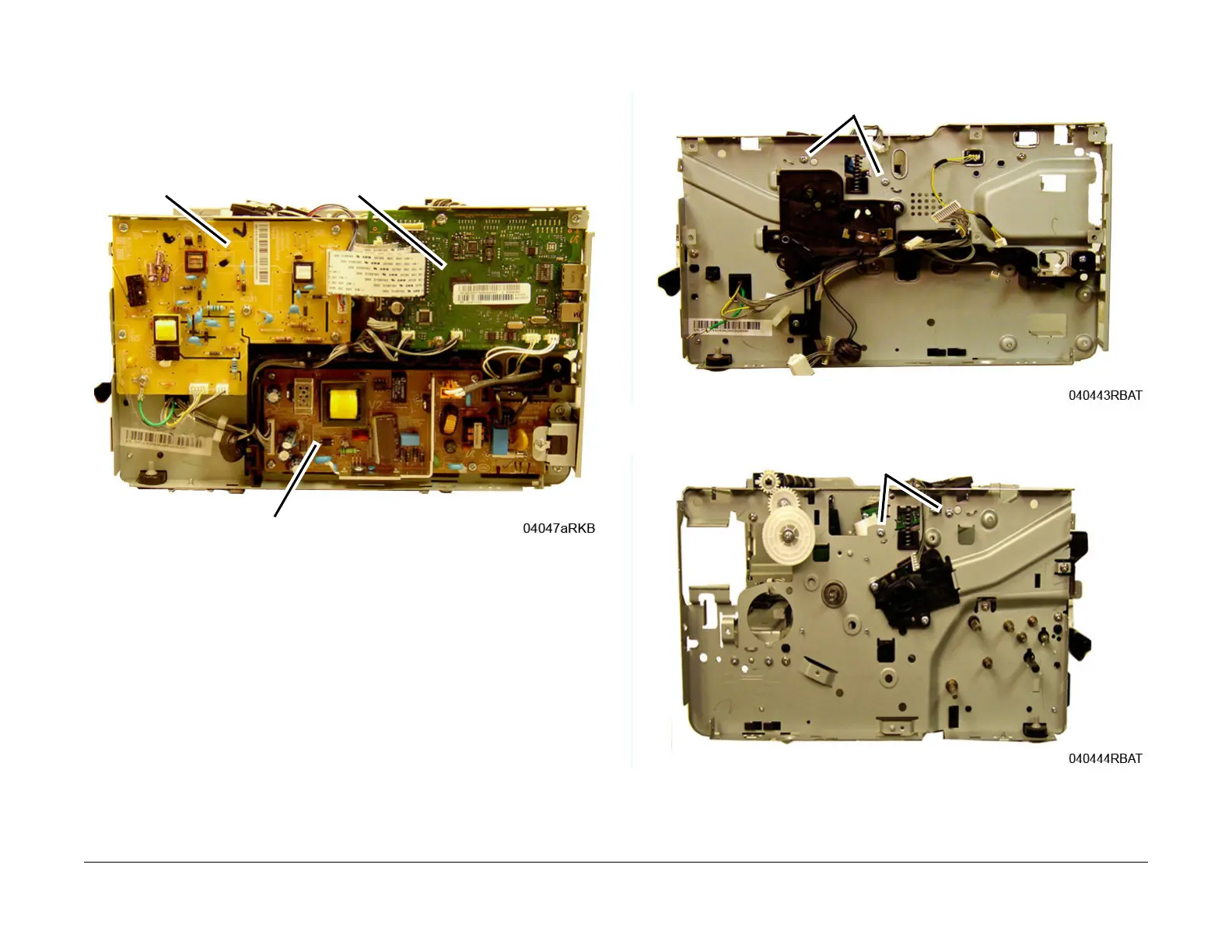
12. Remove the HVPS, LVPS, and Main PWB’s, Figure 6:
a. Disconnect three connectors, three FFCs, remove six screws, then the HVPS PWB.
Remove four contact springs from the high voltage contact guide.
b. Disconnect four connectors, remove six screws, then remove the LVPS PWB.
Remo
ve the insulation (black) pad behind the LVPS PWB.
c. Disconnect seven connectors, three FFCs, remove five screws, then remove t
he
Main PW
B.
Figure 6 PWB Removal
13. Remove two screws on the left frame, F
igure 7, two screws on the right frame, Figure 8,
t
hen remove the LSU Assembly.
Figure 7 LSU Left Side Screws
Figure 8 LSU Right Side Screws
HVPS PWB
Main PWB
LVP S PWB
 Loading...