July 2019
4-23
Xerox® B210 Service Manual
REP 4.9
Repairs - Adjustments
Initial Release
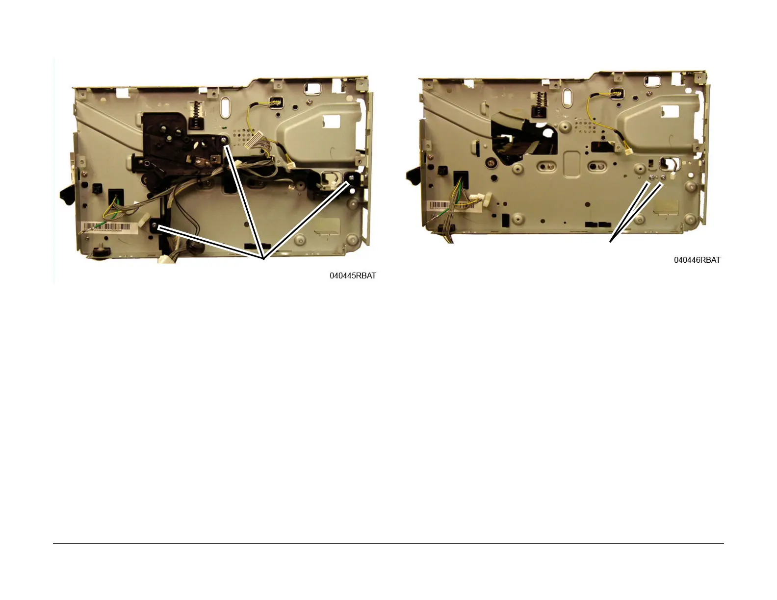
14. Remove two screws on the wire harness guide, the screw securing the high voltage con-
tact guide, then remove the guides, F
igure 9.
Figure 9 Wire Guides and HV Contact Guide
15. Remove two screws from the right frame securing the Exit Sensor Plate, F
igure 10.
Figure 10 Exit Sensor Plate Screws
 Loading...