2-12 Phaser 3140/3155/3160 Printer Service Manual
Theory of Operation
Memory
The Controller Board has Flash and DRAM memory.
• Flash Memory: Stores System Program and can be updated via USB interface.
• DRAM Memory: It is used as Swath Buffer in printing, and System Working
Memory Area.
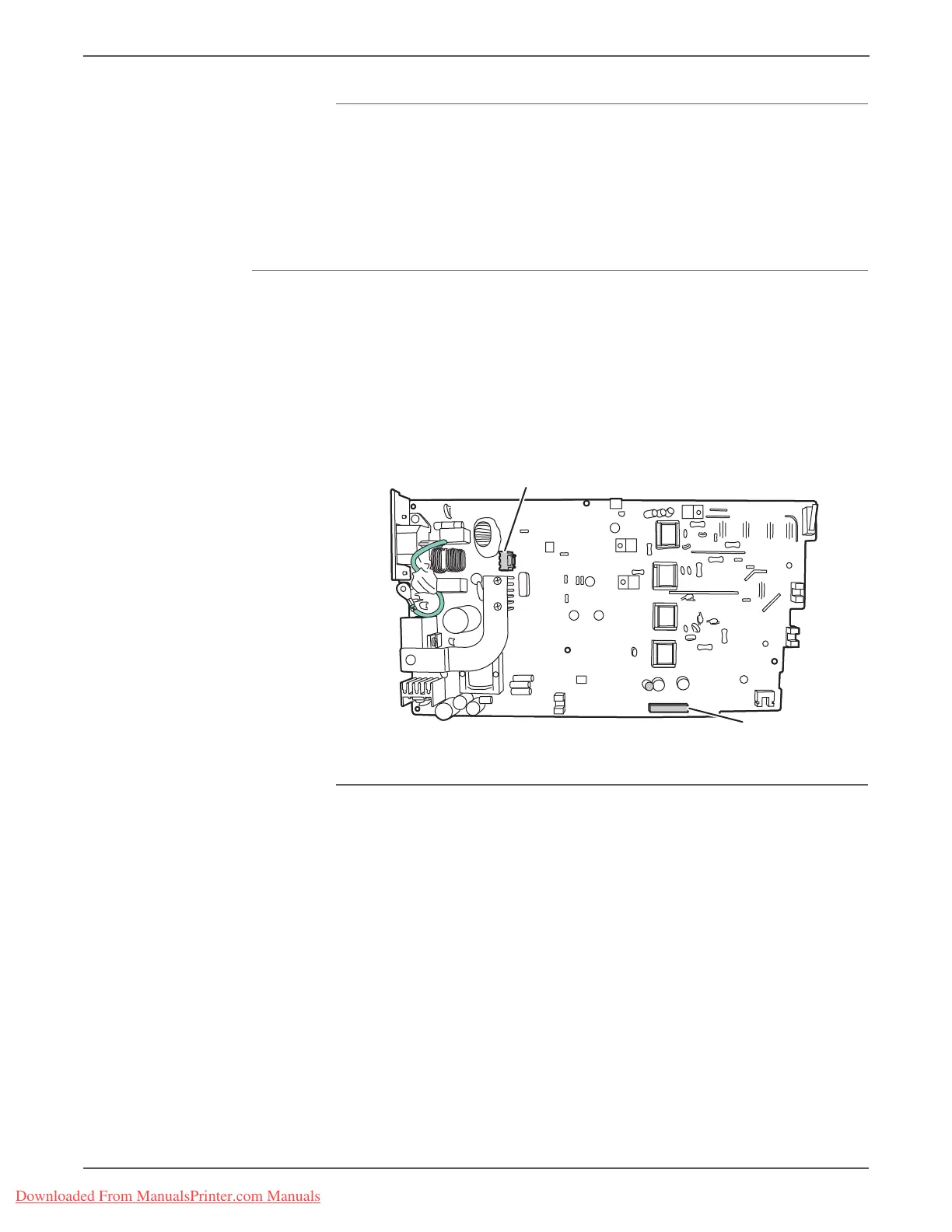
Power Supply Board
The Power Supply board consists of low voltage and high voltage circuitry and
supplies power to the entire printer.
The low voltage circuit supplies DC power to the printer. It converts 110V/220V to
+5V and +24V DC.
The high voltage circuit outputs the high voltage for the THV/MHV/BIAS signals.
The high voltage output is supplied to the Print Cartridge and Transfer Roller.
AC heater control circuitry supplies power to the Fuser.
Transfer High Voltage (THV+)
The (+) Transfer High Voltage is supplied to the Transfer Roller for transferring
toner onto the OPC Drum to the paper.
• Input Voltage: 24 VDC ± 15%
• Output Voltage: MAX +5.0 KV ± 5% (duty variable, no loading)
• Input Contrast of the Voltage Stability Degree: less than ± 3% (fluctuating
input 21.6V~26.4V)
• Loading contrast: ± 3% or less
• Output Voltage Rising Time: 50 ms Max
• Output Voltage Falling Time: 100 ms Max
• Fluctuating Transfer Voltage with Environmental Various: 0 V~5 KV
P/JCON2
P/JCON1
s3160-092
Downloaded From ManualsPrinter.com Manuals

 Loading...