08/2012
7-3
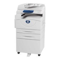
WorkCentre 5021/5019
7.1.1
Wiring Data
Initial Issue
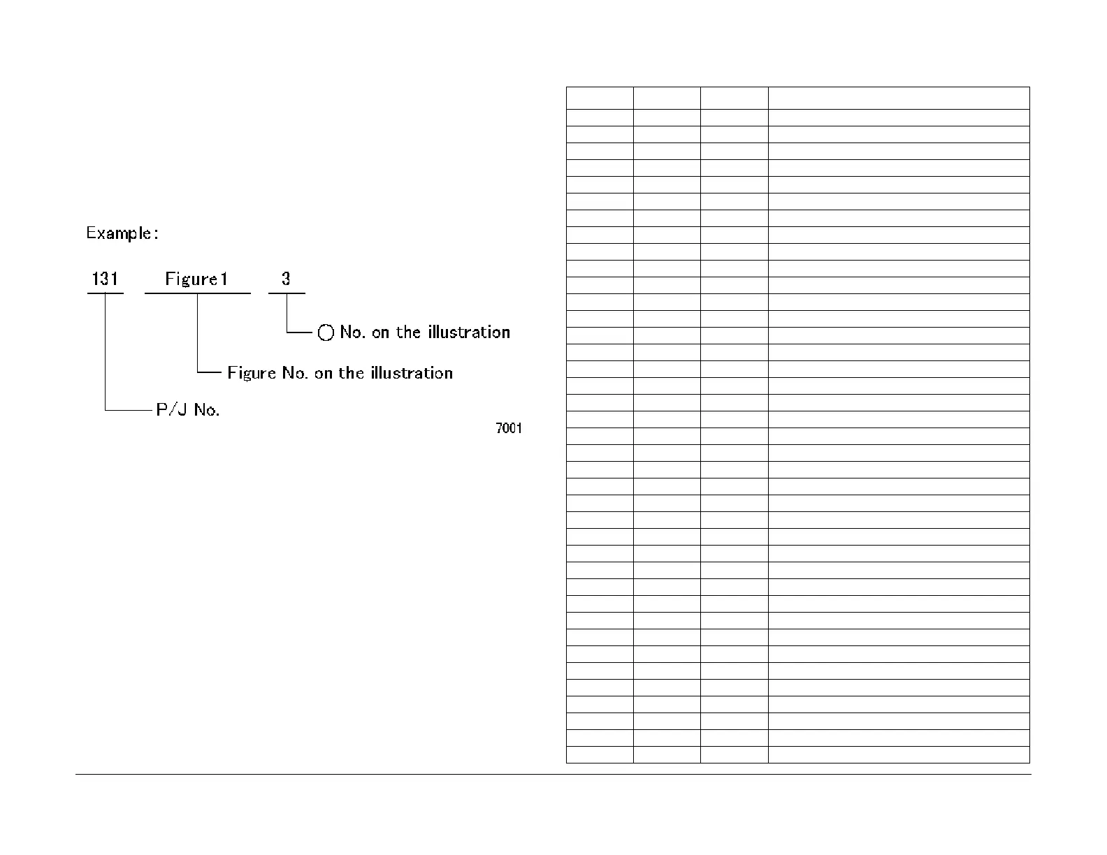
7.1.1 Plug/Jack Location List
How to Use the Plug/Jack Location List
• To find which position to install specific connectors to, refer to the table 'Plug/Jack Loca-
tion List ' for Figure No. and Item No., and then to the figure in 'Plug/Jack Positions.'
• P/J No. on 'Plug/Jack Location List' is expressed in the four ways below:
• J250 represents Jack 250.
• P250 represents Plug 250.
• CN1 represents Connector 1.
• FS1 represents Faston Terminal 1.
Figure 1 7001
Plug/Jack Location List
Table 1 Plug/Jack Location List
P/J Fig Item Remarkes (where to Connect)
JA 5 9 DRUM CRUM PWB
J1 8 9 AC Inlet
J2 8 7 AC Inlet
J3 8 1 Main Power Switch
J4 8 2 Main Power Switch
J5 8 11 Main Power Switch
J6 8 10 Main Power Switch
J7 8 8 AC Inlet
P/J10 4 7 Fusing Unit
P/J100 7 4 L/H Cover Interlock Switch
P/J101 5 1 Front Cover Interlock Switch
P/J101C 9 2 Tray 2 Nudger Level Sensor (1TM)
P/J102C 9 3 Tray 2 No Paper Sensor (1TM)
P/J102 4 2 MSI No Paper Sensor
P/J103 4 10 Fusing Unit Exit Sensor
P/J104 4 1 Regi. Sensor
P/J105 4 3 Tray 1 No Paper Sensor
P/J108 5 10 Front Cover Switch
P/J130 5 3 ROS Motor
P/J140 5 6 LD PWB (8pin)
P/J160 5 5 LD PWB (2pin)
P/J201 57LD PWB
P/J201 7 5 Main Drive Motor (2pin)
P/J202 7 3 Main Drive Motor (8pin)
P/J203 4 6 Duplex Clutch
P/J204 7 6 Regi. Clutch
P/J205 7 7 Tray 1 Feed Clutch
P/J206 44MSI Feed Clutch
P/J207 6 12 ESS/MCU PWB (to Toner Dispense Motor)
P/J208 7 2 Invert Motor
P/J209 6 6 ESS/MCU PWB (to Nohad Fan)
P/J220C 9 1 Tray 2 Feed/Lift Up Motor (1TM)
P/J400 6 19 ESS/MCU PWB
P/J401 6 13 ESS/MCU PWB
P/J402 6 11 ESS/MCU PWB
P/J403 68ESS/MCU PWB
P/J405 67ESS/MCU PWB
P/J406 6 10 ESS/MCU PWB
P/J407 69ESS/MCU PWB