6F65G11
6-50
9
8
7
6
5
4
3
2
1
Shimming
Example:
If “M2” is 27.32 mm and “R” is (+5), then
T2 = 27.32 mm – 26.90 mm – (+5)/100
= 27.32 – 26.90 + 0.05
= 0.47 mm
4. Select the reverse gear shim(s) (T2) as
follows.
Example:
If “T2” is 0.47 mm, then the reverse gear
shim is 0.48 mm.
If “T2” is 0.41 mm, then the reverse gear
shim is 0.42 mm.
Backlash
Measuring the forward and reverse
gear backlash
1. Remove the water pump assembly.
2. Set the gear shift to the neutral position
at the lower unit.
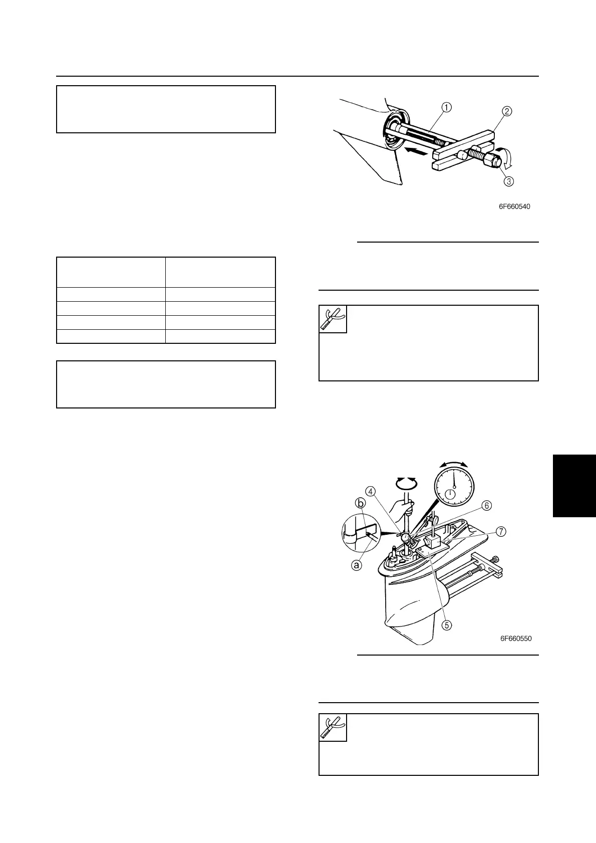
3. Install the special service tools so that it
pushes against the propeller shaft.
NOTE:
Tighten the center bolt while turning the drive
shaft until the drive shaft can no longer be
turned.
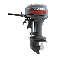
4. Install the backlash indicator onto the
drive shaft (16.0 mm [0.63 in] in diame-
ter), then the dial gauge onto the lower
unit.
NOTE:
Install the dial gauge so that the plunger a
contacts the mark b on the backlash indica-
tor.
Calculation formula:
Reverse gear shim thickness (T2) =
M2 – 26.90 – R/100
Calculated numeral
Rounded numeral
at 1/100th place
1, 2 2
3, 4, 5 5
6, 7, 8 8
9, 10 10
Available shim thicknesses:
0.05, 0.08, 0.12, 0.30, and
0.50 mm
Bearing housing puller claw M 1:
90890-06503
Stopper guide plate 2:
90890-06501
Center bolt 3: 90890-06504
Backlash indicator 4: 90890-06706
Magnet base plate 5: 90890-07003
Dial gauge set 6: 90890-01252
Magnet base B 7: 90890-06844