6F65G11
7-18
9
8
7
6
5
4
3
2
1
Clamp brackets, swivel bracket
Removing the clamp brackets
1. Remove the tilt pin, and then remove the
clamp bracket bolt, clamp bracket nut
and collar.
2. Remove the cap nuts, then the self-lock-
ing nuts and plate.
3. Remove the tilt both stopper plate, cir-
clips and tilt stopper plate shafts.
4. Remove the clamp bracket bolt, then dis-
assemble the clamp brackets.
5. Remove the pins and tilt stopper plates.
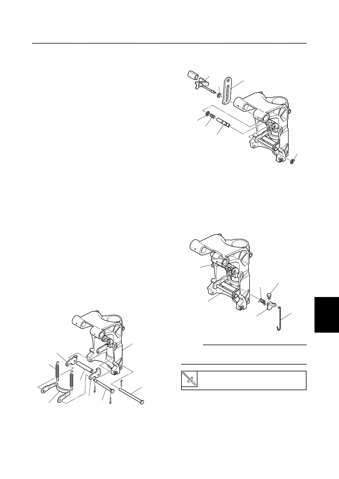
Disassembling the swivel bracket
1. Loosen the bolts, and then remove the
spring, stopper and tilt lock lever.
2. Remove the circlips, tilt lock lever, tilt lock
rod and tilt lock plate.
3. Remove the bushings and collar.
4. Remove the pin 1, pin 2, collar, tilt lock
plates, tilt lock arm, and springs.
Assembling the swivel bracket
1. Install the tilt lock arm 1, tilt lock plates
2, pin 2 3, pin 1 4, collar 5, springs 6
to the swivel bracket 7.
2. Install the plastic washer 8, tilt stopper
plate 9 and then install the tilt lock lever
0 partially into the swivel bracket.
3. Install the circlip q, spring w and collar
e, then install the circlip r.
4. Install the tilt spring t and hook the tilt
lock rod y onto the tilt lever u and the
pin 2 3, and then insert the tilt lever u
into the tilt lock lever 9 completely.
5. Install the bolt i to the tilt lever u.
NOTE:
After installation, check the tilt lock lever for
proper operation.
Installing the clamp brackets
1. Install the bushings, tilt stopper plates,
and pins to the swivel bracket assembly.