GEN
INFO
1-
6F65G11
General information
1-1
How to use this manual
Manual format
The format of this manual has been designed to make service procedures clear and easy to under-
stand. Use the information below as a guide for effective and quality service.
1 Parts are shown and detailed in an exploded diagram and are listed in the components list.
2 Tightening torque specifications are provided in the exploded diagrams and after a numbered
step with tightening instructions.
3 Symbols are used to indicate important aspects of a procedure, such as the grade of lubricant
and lubrication point.
4 The components list consists of part names and quantities, as well as bolt and screw dimensions.
5 Service points regarding removal, checking, and installation are shown in individual illustrations
to explain the relevant procedure.
NOTE:
For troubleshooting procedures, see Chapter 9, “Troubleshooting.”
LOWR
Lower unit
6-5
62Y5A11
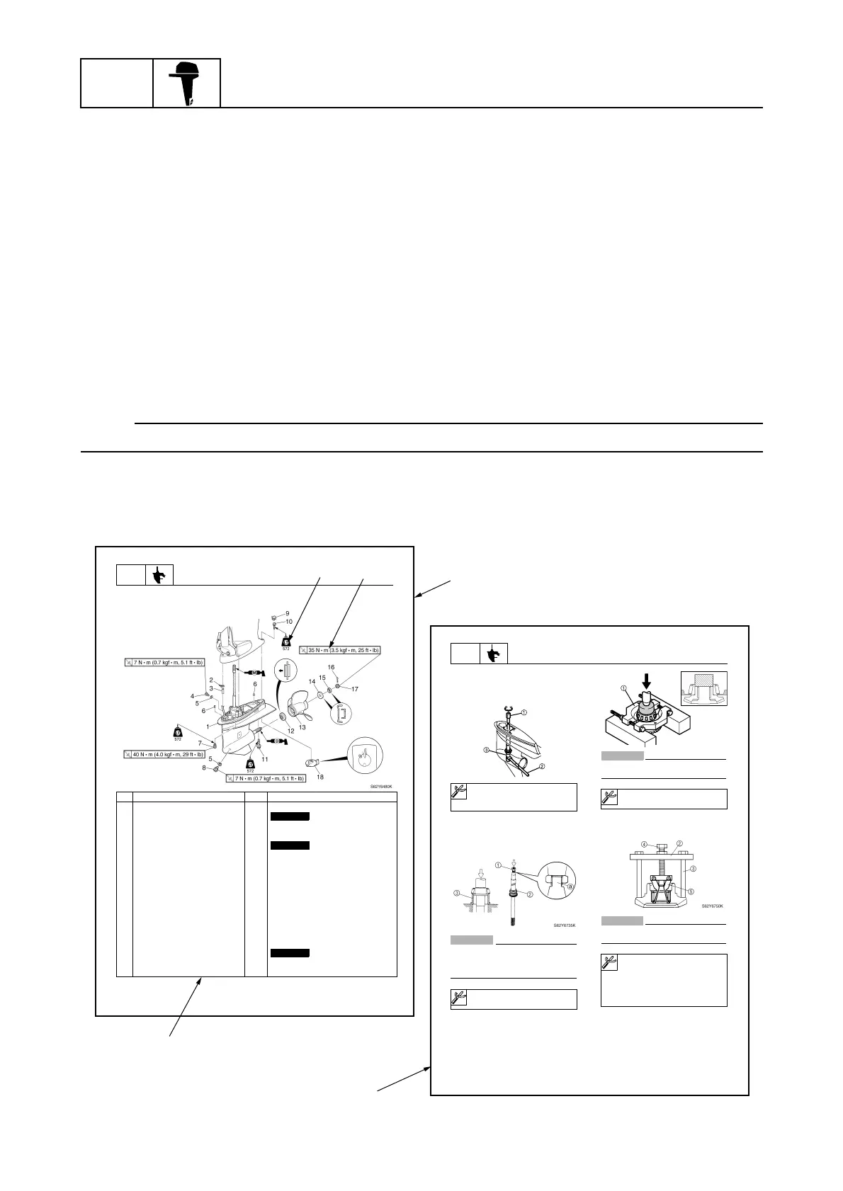
Lower unit
No. Part name Q’ty Remarks
1 Lower unit 1
2 Plastic tie 1
Not reusable
3Hose 1
4 Check screw 1
5 Gasket 2
Not reusable
6 Dowel pin 2
7 Bolt 4 M10 40 mm
8 Drain screw 1
9Grommet 1
10 Bolt 1 M10 45 mm
11 Bolt 1 M8 60 mm
12 Thrust washer 1
13 Propeller 1
14 Washer 1
15 Washer 1
16 Cotter pin 1
Not reusable
17 Propeller nut 1
18 Trim tab 1
LOWR
Lower unit
6-19
62Y5A11
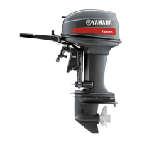
Removing the drive shaft
1. Remove the drive shaft assembly and
pinion, and then pull out the forward
gear.
Disassembling the drive shaft
1. Install the pinion nut , tighten it finger
tight, and then remove the drive shaft
bearing using a press.
CAUTION:
• Do not press the drive shaft threads
directly.
Do not reuse the bearing, always
replace it with a new one.
Disassembling the forward gear
1. Remove the taper roller bearing from the
forward gear using a press.
CAUTION:
Do not reuse the bearing, always replace
it with a new one.
2. Remove the needle bearing from the for-
ward gear.
CAUTION:
Do not reuse the bearing, always replace
it with a new one.
Drive shaft holder 4 : 90890-06518
Pinion nut holder : 90890-06505
Socket adapter 2 : 90890-06507
Bearing inner race attachment :
90890-06639
S62Y6850K
Bearing separator : 90890-06534
Stopper guide plate : 90890-06501
Stopper guide stand :
90890-06538
Bearing puller : 90890-06535
Bearing puller claw 1 :
90890-06536
S62Y6740K
3
2
1
1
2
3
3
2
3
4
5
1
4
5
a
×
×
×
1
2