ELEC
8-11
6F65G11
Electrical systems
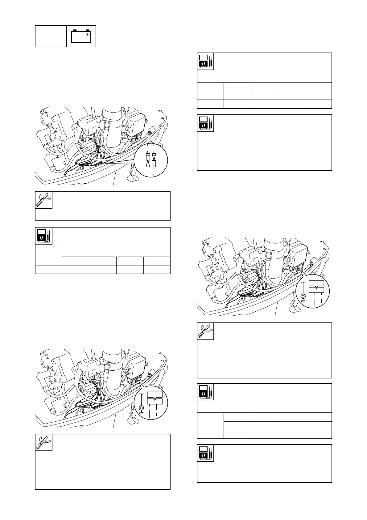
Checking the charge coil
1. Disconnect the CDI unit coupler.
2. Connect the test harness (4 pins) to the
charge coil.
3. Measure the charge coil output peak volt-
age. Replace the charge coil if below
specification.
Pulser coil output peak voltage:
White/red (W/R) — Ground (B)
White/Black (W/B) — Ground (B)
r/min
Unloaded
Loaded
Cranking 1,500 3,500
DC V 10.0 10.0 30.0 70.0
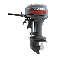
Checking the CDI unit
1. Measure the CDI unit output peak volt-
age. If below specification, measure the
pulser coil output peak voltage. Replace
the CDI unit if the output peak voltage of
the pulser coil is above specification.
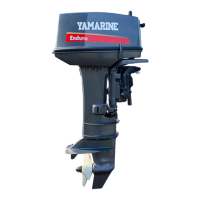
Checking the pulser coils
1. Disconnect the CDI unit coupler.
2. Connect the test harness (4 pins) to the
pulser coil.
3. Measure the pulser coil output peak volt-
age. Replace the pulser coil if below
specification.
Digital circuit tester: 90890-3174
Peak voltage adaptor B:
90890-03172
Digital circuit tester: 90890-3174
Peak voltage adaptor B:
90890-03172
Test harness (4-pins):
New: 90890-06871
Current: 90890-06771
CDI unit output peak voltage:
Orange (O)-ground (B)
r/min
Loaded
Cranking 1,500 3,500
DC V 160 185 170
Pulser coil resistance
(reference data):
White/red (W/R) — Ground (B)
White/Black (W/B) — Ground (B)
16.2 — 19.8 Ω
at 20°C (68°F)
Digital circuit tester: 90890-3174
Peak voltage adaptor B:
90890-03172
Test harness (4-pins):
New: 90890-06871
Current: 90890-06771
Charge coil output peak voltage:
Positive side: Brown (Br) —
Negative side: Blue (L)
r/min
Unloaded
Loaded
Cranking 1,500 3,500
DC V 150 140 190 180
Charge coil resistance
(reference data):
Brown (Br) — Blue (L)
243 — 297 Ω at 20°C (68°F)