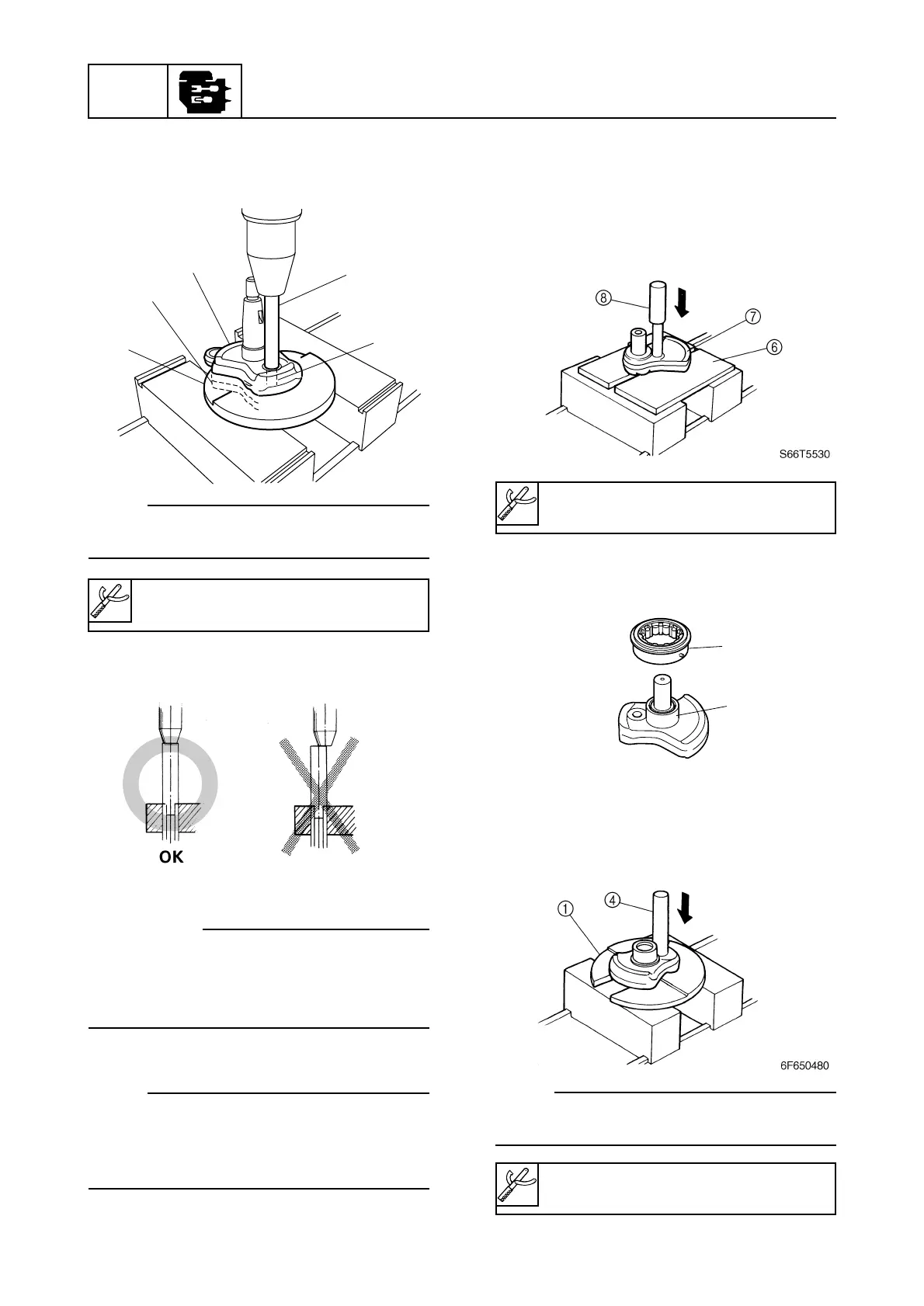
4. Remove the washers, roller bearing and
connecting rod.
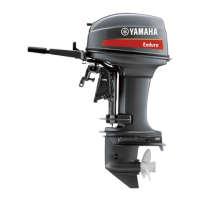
5. Insert the support 6 between crank 2
and 3 7 with crank 3 on top. Place pres-
sure pin B 8 on the shaft, and force it out
using a press.
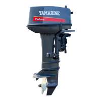
6. Remove the roller bearing 9 from the
inner race 0.
7. Remove the crankpin between cranks 2
and 3 by applying pressure to pressure
pin C using a press.
NOTE:
Pressure pin C should be pressed down
straight.
POWR
5-31
6F65G11
Power unit
Plate C 1: 90890-02402
Pressure pin C 4: 90890-02403
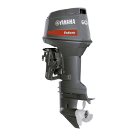
2. Insert the plate C 1 between crank 1 2
and crank 2 3. Place pressure pin C 4
in the end of the crank pin 5.
NOTE:
Remove the bearing before starting this pro-
cedures.
3. Remove the crank pin by applying pres-
sure to pressure pin C 4 with a press.
cC
9 Apply pressure to pressure pin C
slowly.
9 Hold pressure pin C in line with the
press screw spindle.
NOTE:
9 When forcing out the crank pin, use care so
that the crank does not fall.
9 To remove crank 4, follow the same proce-
dure.