4-52
ABS (ANTI-LOCK BRAKE SYSTEM)
EAS30935
CHECKING THE BRAKE PIPES
The following procedure applies to all of the
brake pipes.
1. Check:
• Brake pipe end (flare nut)
Damage → Replace the hydraulic unit as-
sembly, brake pipes, and related parts as a
set.
EAS30200
INSTALLING THE HYDRAULIC UNIT
ASSEMBLY
1. Install:
• Hydraulic unit assembly
ECA21371
Do not remove the rubber plugs or bolts
(M10 × 1.0) installed in the brake hose union
bolt holes before installing the hydraulic unit
assembly.
Do not allow any foreign materials to enter the
hydraulic unit assembly, brake hoses or brake
pipes when installing the hydraulic unit assem-
bly.
a. Install the hydraulic unit assembly “1” on
the hydraulic unit bracket “2”.
b. Tighten the hydraulic unit assembly bolt “3”,
and bolt “4” to the specified torque in this or-
der.
2. Remove:
• Rubber plugs or bolt (M10 × 1.0)
3. Install:
• Hydraulic unit brake pipe
4. Tighten:
• Hydraulic unit brake pipe flare nut
NOTICE
ECA19820
If the brake pipe flare nut does not turn easi-
ly, replace the hydraulic unit assembly,
brake pipes, and related parts as a set.
Do not bend the brake pipe when tightening the
brake pipe flare nuts.
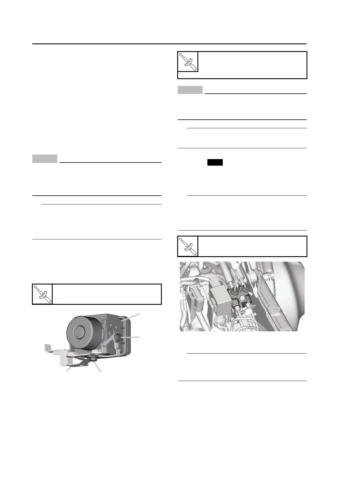
5. Install:
•Gasket
• Brake hose union bolt “1”
• Brake hose
Refer to “CABLE ROUTING” on page 2-15.
After holding the protrusion “a” (17 mm (0.67 in))
on the brake hose joint with an appropriate tool,
tighten the brake hose union bolts to the speci-
fied torque.
6. Connect:
• ABS ECU coupler “1”
Connect the ABS ECU coupler, and then push
the lock lever “a” of the coupler in the direction of
the arrow shown.
Hydraulic unit assembly bolt
7 N·m (0.7 kgf·m, 5.2 lb·ft)
Hydraulic unit brake pipe flare
nut
16 N·m (1.6 kgf·m, 12 lb·ft)
Front brake hose union bolt
30 N·m (3.0 kgf·m, 22 lb·ft)