5-81
CRANKSHAFT AND BALANCER SHAFT
EAS31171
REMOVING THE CRANKSHAFT AND
BALANCER SHAFT
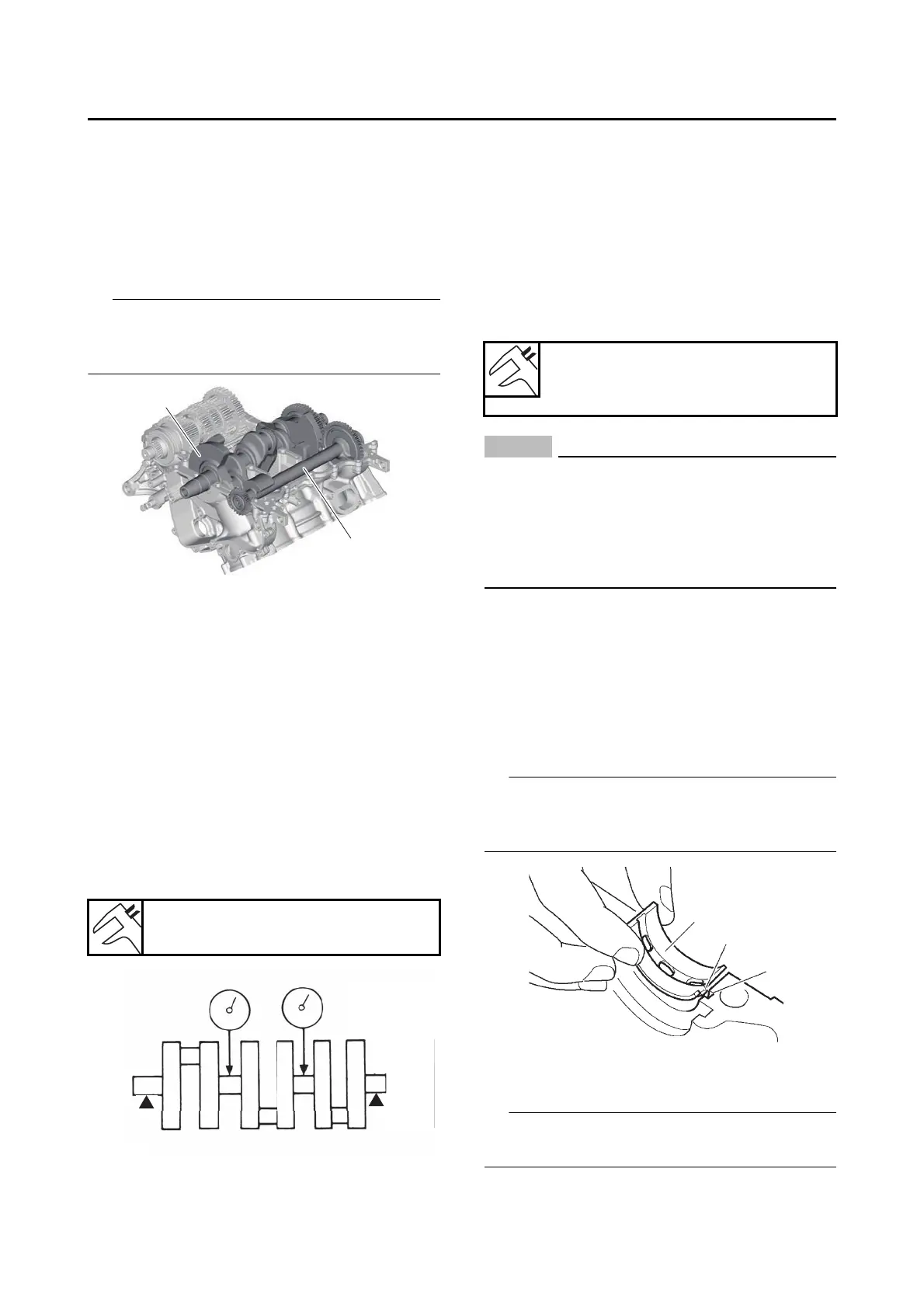
1. Remove:
• Balancer shaft “1”
• Balancer shaft journal bearing
• Crankshaft assembly “2”
• Crankshaft journal bearing
Identify the position of each balancer shaft jour-
nal bearings and crankshaft journal bearings so
that it can be reinstalled in its original place.
EAS31174
CHECKING THE OIL NOZZLES
The following procedure applies to all of the oil
nozzles.
1. Check:
• Oil nozzle
Damage/wear → Replace the oil nozzle.
• Oil passage
Obstruction → Blow out with compressed air.
EAS31075
CHECKING THE CRANKSHAFT
1. Measure:
• Crankshaft runout
Out of specification → Replace the crank-
shaft.
2. Check:
• Crankshaft journal surfaces
• Crankshaft pin surfaces
• Bearing surfaces
Scratches/wear → Replace the crankshaft.
3. Measure:
• Crankshaft-journal-to-crankshaft-journal-
bearing clearance
Out of specification → Replace the crank-
shaft journal bearings.
ECA13920
Do not interchange the crankshaft journal
bearings. To obtain the correct crankshaft-
journal-to-crankshaft-journal-bearing clear-
ance and prevent engine damage, the crank-
shaft journal bearings must be installed in
their original positions.
a. Clean the crankshaft journal bearings,
crankshaft journals, and bearing portions of
the crankcase.
b. Place the upper crankcase upside down on
a bench.
c. Install the crankshaft journal upper bear-
ings “1” and the crankshaft into the upper
crankcase.
Align the projections “a” on the crankshaft jour-
nal upper bearings with the notches “b” in the up-
per crankcase.
d. Put a piece of Plastigauge® “1” on each
crankshaft journal.
Do not put the Plastigauge® over the oil hole in
the crankshaft journal.
Runout limit
0.030 mm (0.0012 in)
Journal oil clearance
0.013–0.037 mm (0.0005–0.0015
in)