8-59
ELECTRICAL COMPONENTS
c. Check the relay unit (diode) for continuity.
d. Check the relay unit (diode) for no continui-
ty.
EAS30558
CHECKING THE IGNITION COILS
The following procedure applies to all of the igni-
tion coils.
1. Check:
• Primary coil resistance
Out of specification → Replace.
a. Disconnect the ignition coil coupler from the
ignition coil.
b. Connect the digital circuit tester (Ω) to the
ignition coil as shown.
c. Measure the primary coil resistance.
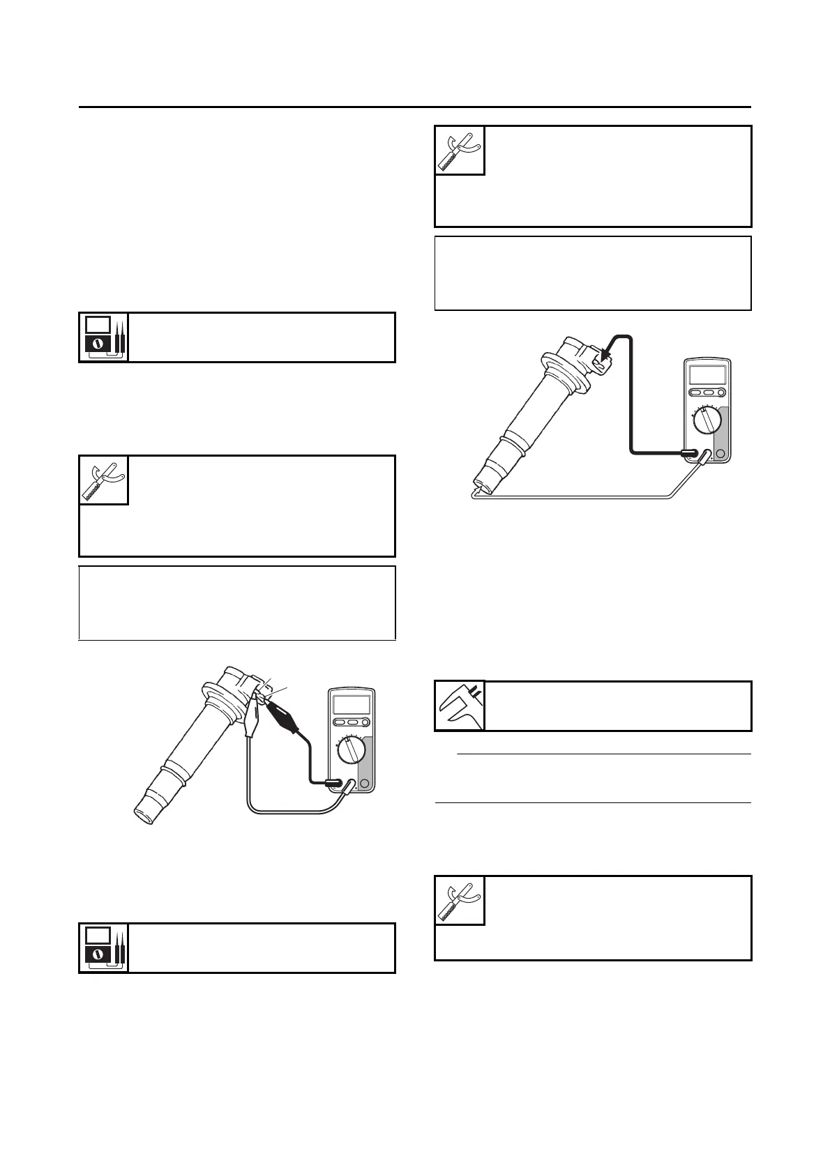
2. Check:
• Secondary coil resistance
Out of specification → Replace.
a. Connect the digital circuit tester (Ω) to the
ignition coil as shown.
b. Measure the secondary coil resistance.
EAS30556
CHECKING THE IGNITION SPARK GAP
1. Check:
• Ignition spark gap
Out of specification → Perform the ignition
system troubleshooting, starting with step (5).
Refer to “TROUBLESHOOTING” on page 8-
6.
If the ignition spark gap is within specification,
the ignition system circuit is operating normally.
a. Remove the ignition coil from the spark
plug.
b. Connect the ignition checker “1” as shown.
Primary coil resistance
1.19–1.61 Ω
Digital circuit tester (CD732)
90890-03243
Model 88 Multimeter with ta-
chometer
YU-A1927
• Positive tester probe
Ignition coil terminal “1”
• Negative tester probe
Ignition coil terminal “2”
Secondary coil resistance
8.50–11.50 kΩ
Digital circuit tester (CD732)
90890-03243
Model 88 Multimeter with ta-
chometer
YU-A1927
• Negative tester probe
Ignition coil terminal “1”
• Positive tester probe
Spark plug terminal “2”
Minimum ignition spark gap
6.0 mm (0.24 in)
Ignition checker
90890-06754
Oppama pet–4000 spark checker
YM-34487