8-65
ELECTRICAL COMPONENTS
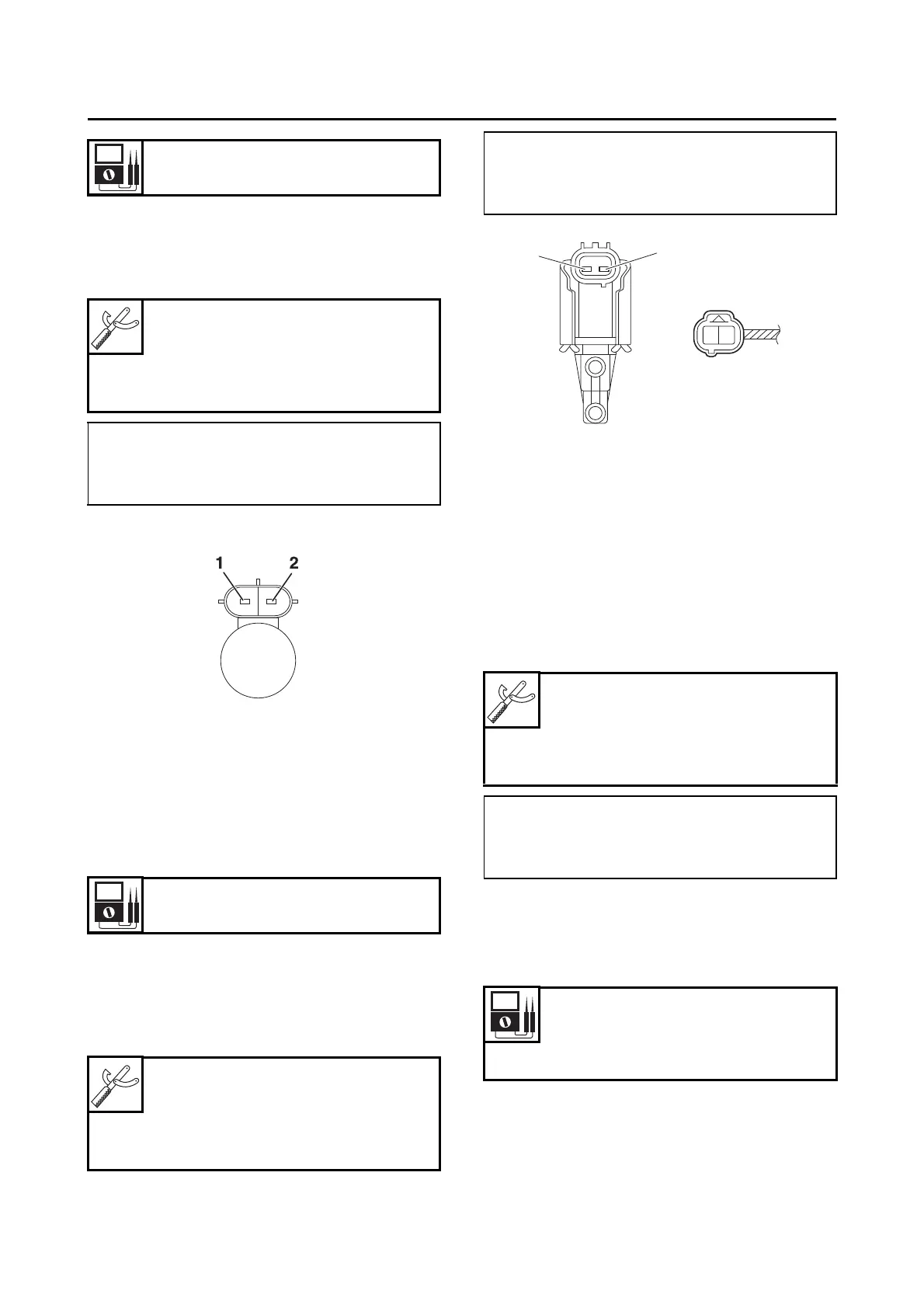
a. Disconnect the fuel injector coupler from
the fuel injector.
b. Connect the digital circuit tester (Ω) to the
fuel injector coupler as shown.
c. Measure the fuel injector resistance.
EAS32604
CHECKING THE PURGE CUT VALVE
SOLENOID
1. Check:
• Purge cut valve solenoid resistance
Out of specification → Replace.
a. Disconnect the purge cut valve solenoid
coupler from the wire harness.
b. Connect the digital circuit tester to the
purge cut valve solenoid terminals as
shown.
c. Measure the purge cut valve solenoid resis-
tance.
EAS31673
CHECKING THE WHEEL SWITCH
1. Check:
• Wheel switch “1” output voltage
Out of specification → Replace the right han-
dlebar switch.
a. Connect the digital circuit tester (DC V) to
the handlebar switch coupler (right) as
shown.
b. Turn the main switch to “ON”.
c. When turning the wheel switch in direction
“a” and “b”, check that the output voltage is
within the specified values.
d. Connect the digital circuit tester (DC V) to
the handlebar switch coupler (right) as
shown.
Resistance
12.0 Ω
Digital circuit tester (CD732)
90890-03243
Model 88 Multimeter with ta-
chometer
YU-A1927
• Positive tester probe →
Injector terminal “1”
• Negative tester probe →
Injector terminal “2”
Solenoid resistance
22–26 Ω
Digital circuit tester (CD732)
90890-03243
Model 88 Multimeter with ta-
chometer
YU-A1927
• Positive tester probe →
Purge cut valve solenoid terminal “1”
• Negative tester probe →
Purge cut valve solenoid terminal “2”
Digital circuit tester (CD732)
90890-03243
Model 88 Multimeter with ta-
chometer
YU-A1927
• Positive tester probe
white/green “2”
• Negative tester probe
black/white “3”
Output voltage reading cycle
More than 5 V to less than 0.5 V
then back to more than 5 V to
less than 0.5 V