5-67
CRANKCASE
8. Tighten:
• Crankcase bolt “9”–“31”
Tighten the bolts in the tightening sequence cast
on the crankcase.
EAS31071
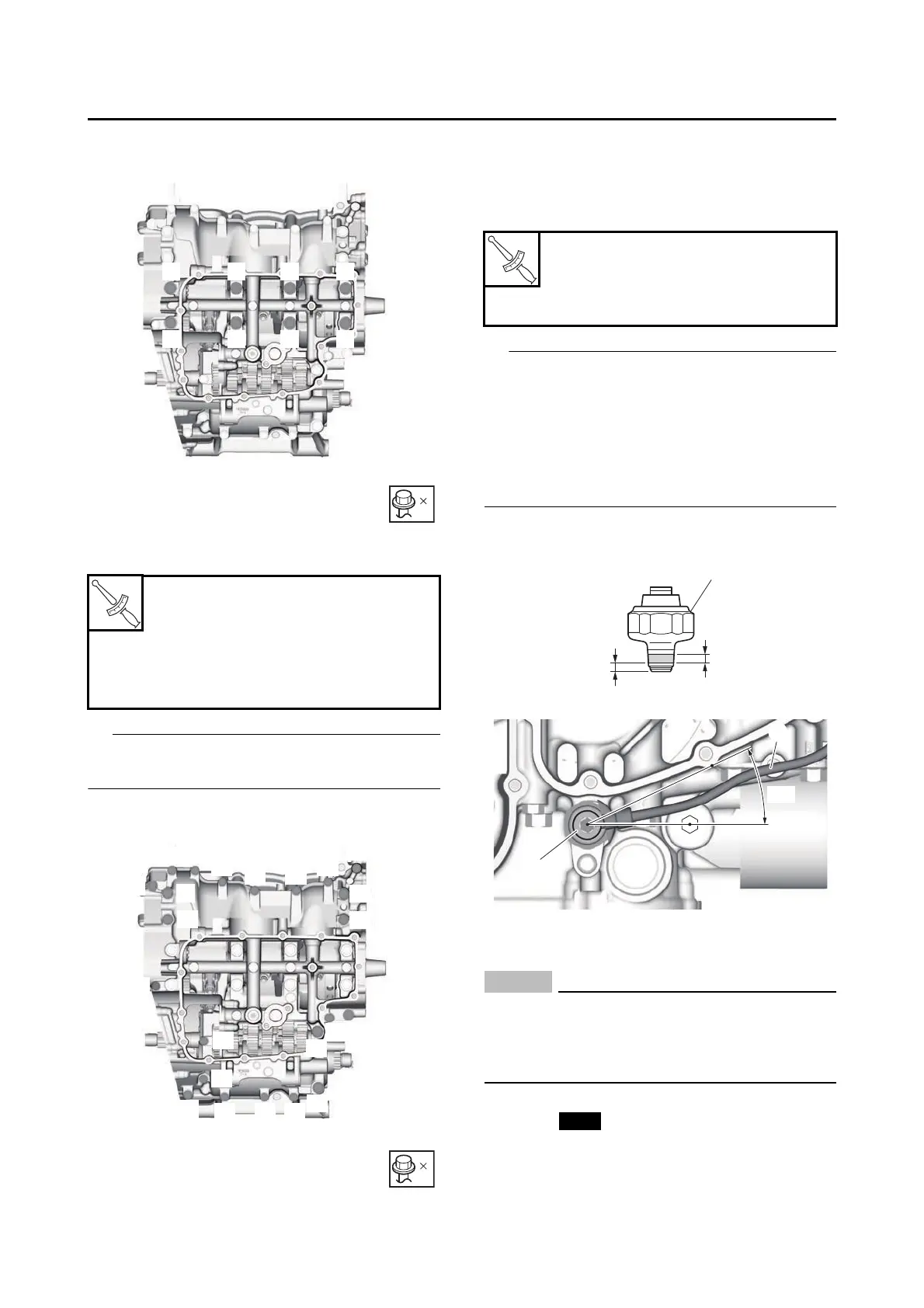
INSTALLING THE OIL PRESSURE SWITCH
1. Install:
• Oil pressure switch “1”
• Oil pressure switch lead “2”
• Apply Three Bond No. 1215B® to the threads
“a” of the oil pressure switch. However, do not
apply Three Bond No. 1215B® to the portion
“b” of the oil pressure switch.
• Install the oil pressure switch lead so that it is
routed within the range shown in the illustra-
tion.
EAS31658
INSTALLING THE GEAR POSITION SENSOR
NOTICE
ECA22630
To prevent damage to the gear position sen-
sor, keep magnets (including any pickup tool
with a magnet, magnetized screwdrivers,
etc.) away from the gear position sensor.
1. Install:
• O-ring
• Gear position sensor “1”
Crankcase bolts “9”–“12”
22 N·m (2.2 kgf·m, 16 lb·ft)
Crankcase bolts “13”–“14”
24 N·m (2.4 kgf·m, 18 lb·ft)
Crankcase bolts “15”–“31”
10 N·m (1.0 kgf·m, 7.4 lb·ft)
23
9
10
12
11
13
14
15
16
17
18
19
20
21
22
23
24
25
26
272829
30
31
Oil pressure switch
13 N·m (1.3 kgf·m, 9.6 lb·ft)
Oil pressure switch lead bolt
1.8 N·m (0.18 kgf·m, 1.3 lb·ft)