5-70
CONNECTING RODS AND PISTONS
EAS30745
REMOVING THE CONNECTING RODS AND
PISTONS
The following procedure applies to all of the con-
necting rods and pistons.
1. Remove:
• Connecting rod cap
• Connecting rod
• Big end bearing
• Identify the position of each big end bearing so
that it can be reinstalled in its original place.
• After removing the connecting rods and con-
necting rod caps, care should be taken not to
damage the mating surfaces of the connecting
rods and connecting rod caps.
2. Remove:
• Piston pin clip
• Piston pin “1”
• Piston “2”
ECA13810
Do not use a hammer to drive the piston pin
out.
• For reference during installation, put identifica-
tion marks on the piston crown.
• Before removing the piston pin, deburr the pis-
ton pin clip groove and the piston pin bore ar-
ea. If both areas are deburred and the piston
pin is still difficult to remove, remove it with the
piston pin puller set “3”.
3. Remove:
• Top ring
• 2nd ring
•Oil ring
When removing a piston ring, open the end gap
with your fingers and lift the other side of the ring
over the piston crown.
EAS30747
CHECKING THE CYLINDER AND PISTON
1. Check:
• Piston wall
• Cylinder wall
Vertical scratches → Replace the cylinder,
and replace the piston and piston rings as a
set.
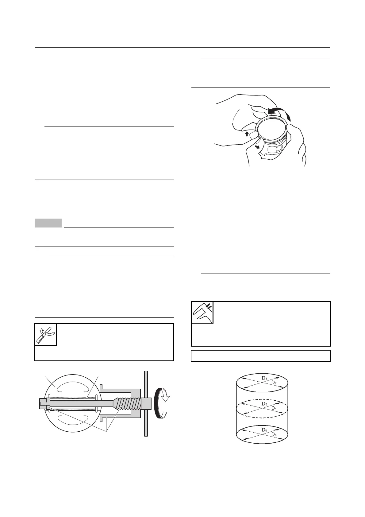
2. Measure:
• Piston-to-cylinder clearance
a. Measure cylinder bore “C” with the cylinder
bore gauge.
Measure cylinder bore “C” by taking side-to-side
and front-to-back measurements of the cylinder.
b. If out of specification, replace the cylinder,
and replace the piston and piston rings as a
set.
Piston pin puller set
90890-01304
Piston pin puller
YU-01304
Bore
78.000–78.010 mm (3.0709–
3.0713 in)
Wear limit
78.060 mm (3.0732 in)
“C” = maximum of D
1
, D
2
, D
3
, D
4
, D
5
, D
6