8-62
ELECTRICAL COMPONENTS
a. Connect the digital circuit tester (DC V) to
the battery as shown.
b. Start the engine and let it run at approxi-
mately 5000 r/min.
c. Measure the charging voltage.
EAS30569
CHECKING THE HORN
1. Check:
• Horn sound
Faulty sound → Replace.
EAS30573
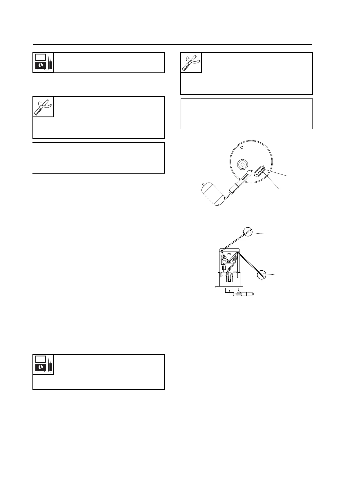
CHECKING THE FUEL SENDER
1. Disconnect:
• Fuel pump coupler
(from the fuel pump)
2. Remove:
• Fuel tank
3. Remove:
• Fuel pump
(from the fuel tank)
4. Check:
• Fuel sender resistance
Out of specification → Replace the fuel pump
assembly.
a. Connect the digital circuit tester (Ω) to the
fuel sender terminals as shown.
b. Move the fuel sender float to maximum “3”
and minimum “4” level position.
EAS30574
CHECKING THE FUEL LEVEL WARNING
LIGHT
This model is equipped with a self-diagnosis de-
vice for the fuel level detection circuit.
1. Check:
• Fuel level warning light “1”
(Turn the main switch to “ON”.)
Warning light comes on for a few seconds,
then goes off → Warning light is OK.
Warning light does not come on → Replace
the meter assembly.
Warning light flashes eight times, then goes
off for 3 seconds in a repeated cycle (mal-
function detected in fuel sender) → Replace
the fuel pump assembly.
Regulated voltage (DC)
14.3–14.7 V
Digital circuit tester (CD732)
90890-03243
Model 88 Multimeter with ta-
chometer
YU-A1927
• Positive tester probe →
Positive battery terminal
• Negative tester probe →
Negative battery terminal
Sender unit resistance (full)
9.0–11.0 Ω
Sender unit resistance (empty)
213.0–219.0 Ω
Digital circuit tester (CD732)
90890-03243
Model 88 Multimeter with ta-
chometer
YU-A1927
• Positive tester probe →
Fuel sender terminal “1”
• Negative tester probe →
Fuel sender terminal “2”