5-82
CRANKSHAFT AND BALANCER SHAFT
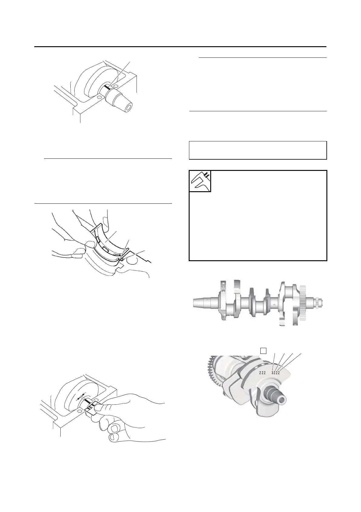
e. Install the crankshaft journal lower bearings
“1” into the lower crankcase and assemble
the crankcase halves.
• Align the projections “a” of the crankshaft jour-
nal lower bearings with the notches “b” in the
lower crankcase.
• Do not move the crankshaft until the clearance
measurement has been completed.
f. Tighten the bolts to specification in the tight-
ening sequence cast on the crankcase.
Refer to “CRANKCASE” on page 5-63.
g. Remove the lower crankcase and the
crankshaft journal lower bearings.
h. Measure the compressed Plastigauge®
width “a” on each crankshaft journal.
If the crankshaft-journal-to-crankshaft-jour-
nal-bearing clearance is out of specifica-
tion, select replacement crankshaft journal
bearings.
4. Select:
• Crankshaft journal bearing (J
1
–J
4
)
• The numbers “A” stamped into the crankshaft
web and the numbers “B” stamped into the
lower crankcase are used to determine the re-
placement crankshaft journal bearing sizes.
•“J
1
”–“J
4
” refer to the bearings shown in the
crankshaft and lower crankcase illustration.
For example, if the crankcase “J
1
” and crank-
shaft web “J
1
” numbers are 7 and 2 respec-
tively, then the bearing size for “J
1
” is:
“J
1
” (crankcase) - “J
1
” (crankshaft web) -1 = 7
- 2 - 1 = 4 (green)
Bearing color code
Code 0
White
Code 1
Blue
Code 2
Black
Code 3
Brown
Code 4
Green