9-228
P1601
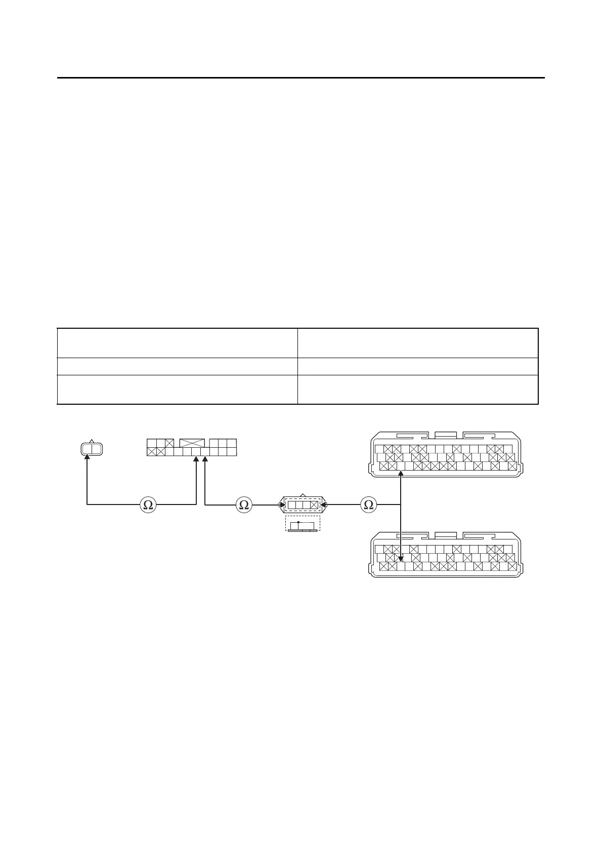
4. Wire harness continuity.
• Disconnect the relay unit coupler “1”, ECU coupler “2” and sidestand switch coupler “3”.
• Remove the joint coupler cap “4”.
• Open circuit check
Is the coupler condition normal?
YES
→ Go to step 4.
NO
a. Connect the coupler securely or replace the wire harness.
b. Turn the main switch to “ON”, and then extend and retract the sidestand.
c. Check the condition of the DTC using the malfunction mode of the YDT.
Is it in the “Recovered” condition?
YES
→ Go to step 7, and complete the service.
NO
→ Go to step 4.
Between relay unit coupler “1” and joint coupler
cap “4”
blue–blue
Between joint coupler “4” and ECU coupler “2” blue/yellow–blue/yellow
Between relay unit coupler “1” and sidestand
switch coupler “3”
blue/black–blue/black
Gy
LLVP
P/WLg/LY/LL/B
B/LB/LBr/WGy/GG/LB/YL/W
W/YW/GG/WG/WL/WL/Y
L/B
B
W
L/W
R
L/B
LB
Sb/W
Sb
W
Br
L/W
RR
Gy
LLVP
P/WLg/LO/WY/LL/B
B/LB/LBr/WGy/GG/LBr/LB/YL/W
W/YW/GG/WG/WLg/BL/WL/Y
L/Y
L
L/Y
31
4
2
*
2
**
*. MTN890
**. MTN890D
Is resistance 0 Ω?
YES
→ Go to “Short circuit check”.
NO
a. Replace the wire harness.
b. Turn the main switch to “ON”, and then extend and retract the sidestand.
c. Check the condition of the DTC using the malfunction mode of the YDT.