9-261
U0155 or Err
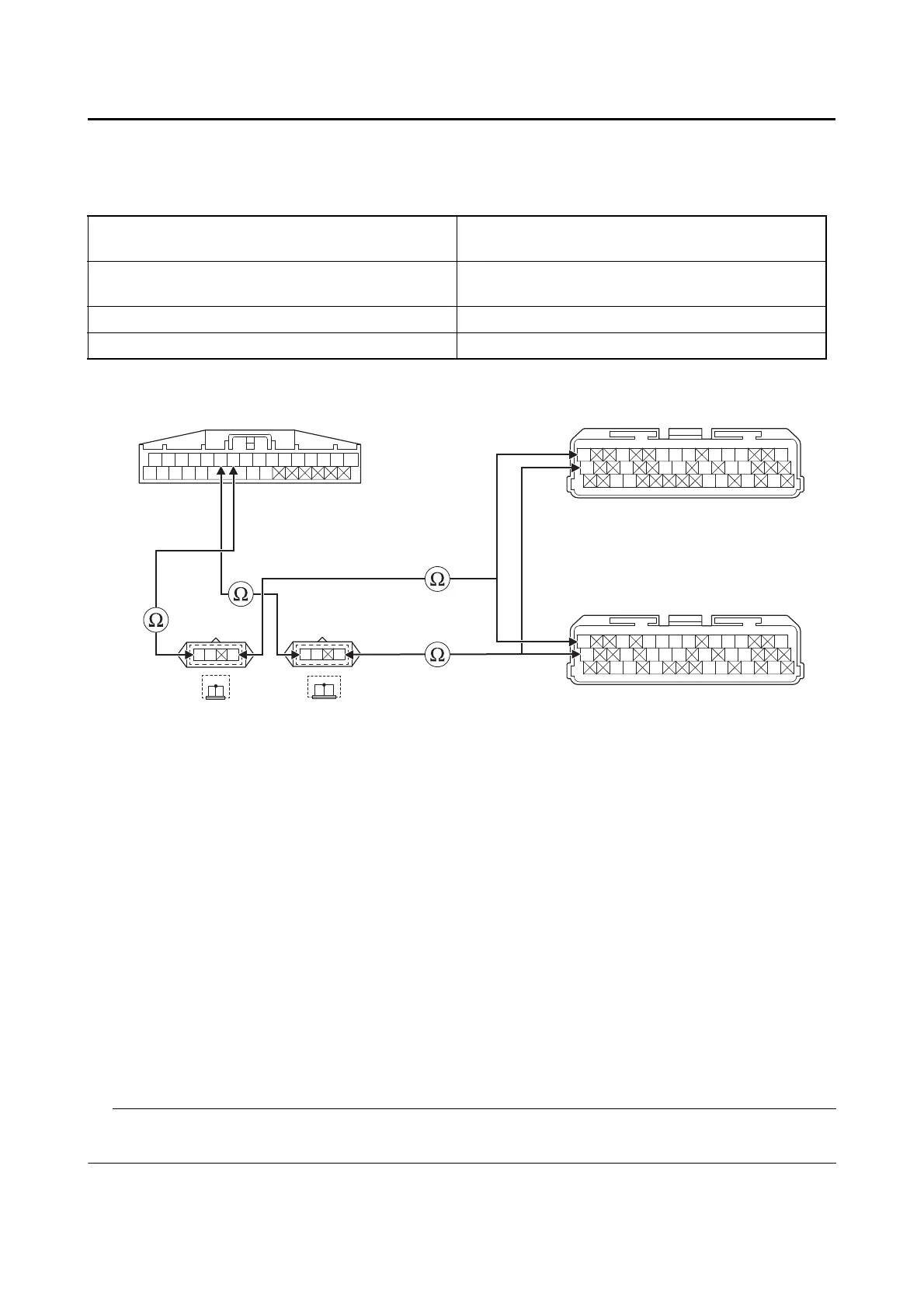
3. Wire harness continuity.
• Disconnect the meter assembly coupler “1” and ECU coupler “4”.
• Remove the joint coupler cap “2” and joint coupler cap “3”.
• Open circuit check
• Short circuit check
Disconnect the ECU related connectors before checking.
Refer to “PARTS CONNECTED TO THE ECU” on page 9-4.
Between meter assembly coupler “1” and joint
coupler “2”
blue/black–blue/black
Between meter assembly coupler “1” and joint
coupler “3”
blue/white–blue/white
Between joint coupler “2” and ECU coupler “4” blue/black–blue/black
Between joint coupler “3” and ECU coupler “4” blue/white–blue/white
Gy
LLVP
P/WLg/LO/WY/LL/B
B/LB/LBr/WGy/GG/LBr/LB/YL/W
W/YW/GG/WG/WLg/BL/WL/Y
R/G R/G R/W B/W
Lg
L/W L/B G/W
Y
W/G W/R G/B
W
W/G W/B Sb/W
G/L W/Y W/L Br/L
B
G/O Br/W Br/B
GBr
L/B L/BY/B
L/W L/WW
Gy
LLVP
P/WLg/LY/LL/B
B/LB/LBr/WGy/GG/LB/YL/W
W/YW/GG/WG/WL/WL/Y
4
*
4
**
1
23
*. MTN890
**. MTN890D
Is resistance 0 Ω?
YES
→ Go to “Short circuit check”.
NO
a. Replace the wire harness.
b. Turn the main switch to “ON”, and then check the condition of the DTC using the malfunction
mode of the YDT.
Is it in the “Recovered” condition?
YES
→ Go to step 6, and complete the service.
NO
→ Go to “Short circuit check”.