12.2 Magnetic Contactors
12-9
12
SERVOPACK Peripheral Devices
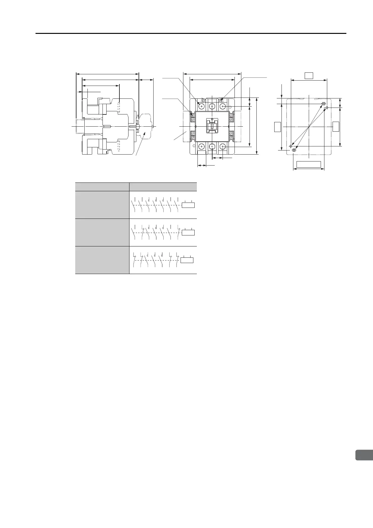
Model: SC-N2S or SC-N3
• You can use either of the following two mount-
ing methods.
: 70 × 75
: (55 to) 60 × 90
• Mounting screws: 2 × M4
Use two mounting holes in diagonally opposing
corners to mount the Magnetic Contactor.
Unit: mm
Approx. mass: 1.1 kg
Mounting Hole
Dimensional Diagram
10.5
20.5
16.8
60 (55 min.)
72.5
(28)
18
111
10.5
88
90
(112)*
121 (for a rail height of 15)
*: With two side-on auxiliary contact blocks mounted.
Main
terminals
M6
Auxiliary
terminal
M3.5
Coil
terminal
M3.5
With auxiliary
contact block
mounted
*
70
75
78
110
16.5
Auxiliary Contacts Contact Structure
4NO
2NO/2NC
4NC
A1 A2
13
14 22 2/T1 4/T2 6/T3 44 32
21 1/L1 3/L2 5/L3 43 31
A1 A2
13
14 22 2/T1 4/T2 6/T3 44 32
21 1/L1 3/L2 5/L3 43 31
A1 A2
13
14 22 2/T1 4/T2 6/T3 44 32
21 1/L1 3/L2 5/L3 43 31

 Loading...


