3 Servomotor Specifications and Dimensional Drawings
3.19.1 SGMCS Servomotors φ135 Model
3-126
3.19 Dimensional Drawings of SGMCS Servomotors
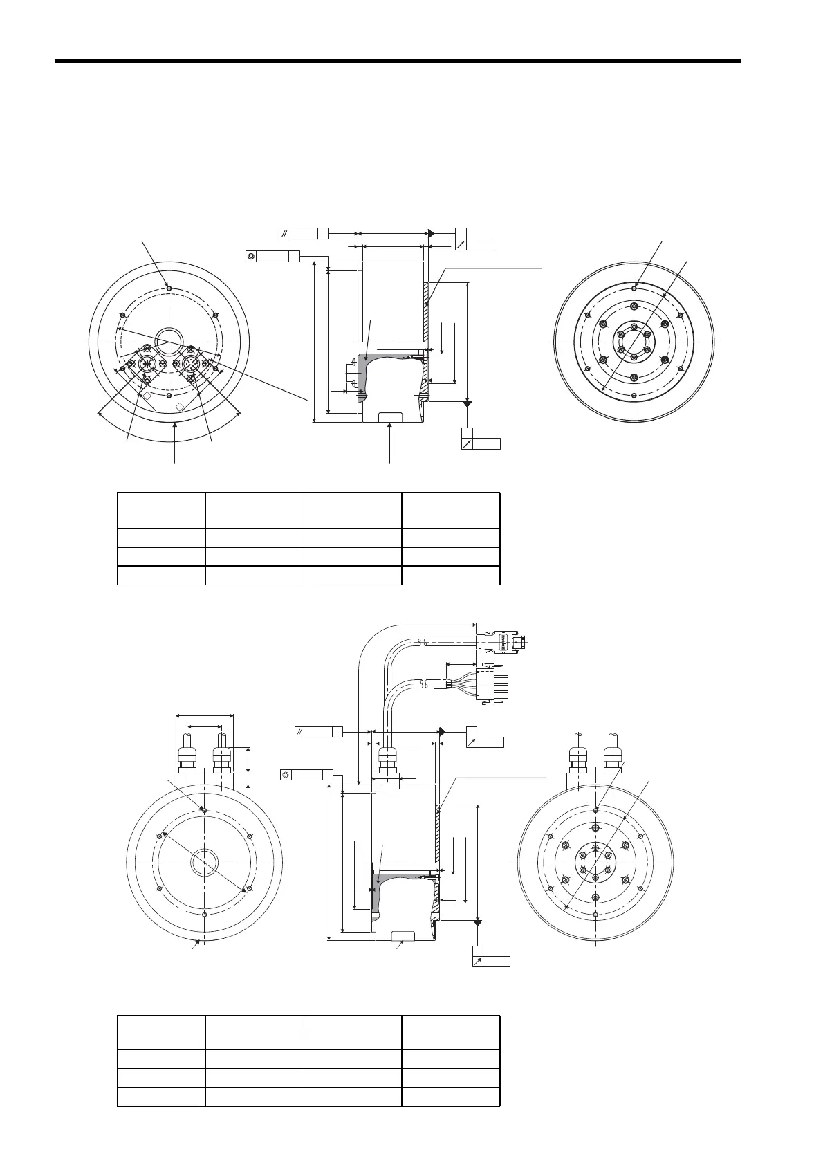
3.19.1 SGMCS Servomotors φ135 Model
(1) Applicable flange: 1
(2) Applicable flange: 4
φ
20
+0.4
0
(0.5: Bolt section)
0.04
A
B
0.02
A
φ0.07
0.07 B
4
(LL)
L
4
±
0.9
φ
135
φ
120h7
(
9
)
(
1
)
φ
100h7
φ
90
90
°
R26
R40.5MAX.
Connector area
φ90
25.4
23.4
(
φ
70
)
6
×
M4 tapped, depth 8
(Divided into six equal sections
of sixty degrees)
6
×
M4 tapped, depth 8
(Divided into six equal sections
of sixty degrees)
(shown with hatching)
Rotating section
Non-
rotating
section
Encoder-end
connector
Servomotor-end
connector
Nameplate
Nameplate
φ120h7: φ120
-0.035
0
φ100h7: φ100
-0.035
0
Units: mm
Model
SGMCS-
L(LL)
Approx. Mass
kg
02B
C11
59 51 4.8
05B
C11
88 80 5.8
07B
C11
128 120 8.2
30
50
(
22
)
10
90
φ
90
φ
4
20
(LL)
L
(
1
)
0.1
(
35
)
300
±
50
4
±
0.9
0.07
B
A
0.07
φ
135
φ
120h7
φ
B
0.02
100h7
φ
A
0.04
20
+0.4
0
φ
(
70
)
φ
(
80
)
φ
6
×
M4 tapped, depth 8
(Divided into six equal
sections of sixty degree)
6
×
M4 tapped, depth 8
(Divided into six equal
sections of sixty degrees)
(0.5: Bolt section)
(shown with hatching)
Rotating section
Non-
rotating
section
Nameplate
Nameplate
φ120h7: φ120
-0.035
0
φ100h7: φ100
-0.035
0
Units: mm
Model
SGMCS-
L(LL)
Approx. Mass
kg
02B
C41
59 51 4.8
05B
C41
88 80 5.8
07B
C41
128 120 8.2