8 Operation
8.5.7 Encoder Signal Output
8-46
8.5.7 Encoder Signal Output
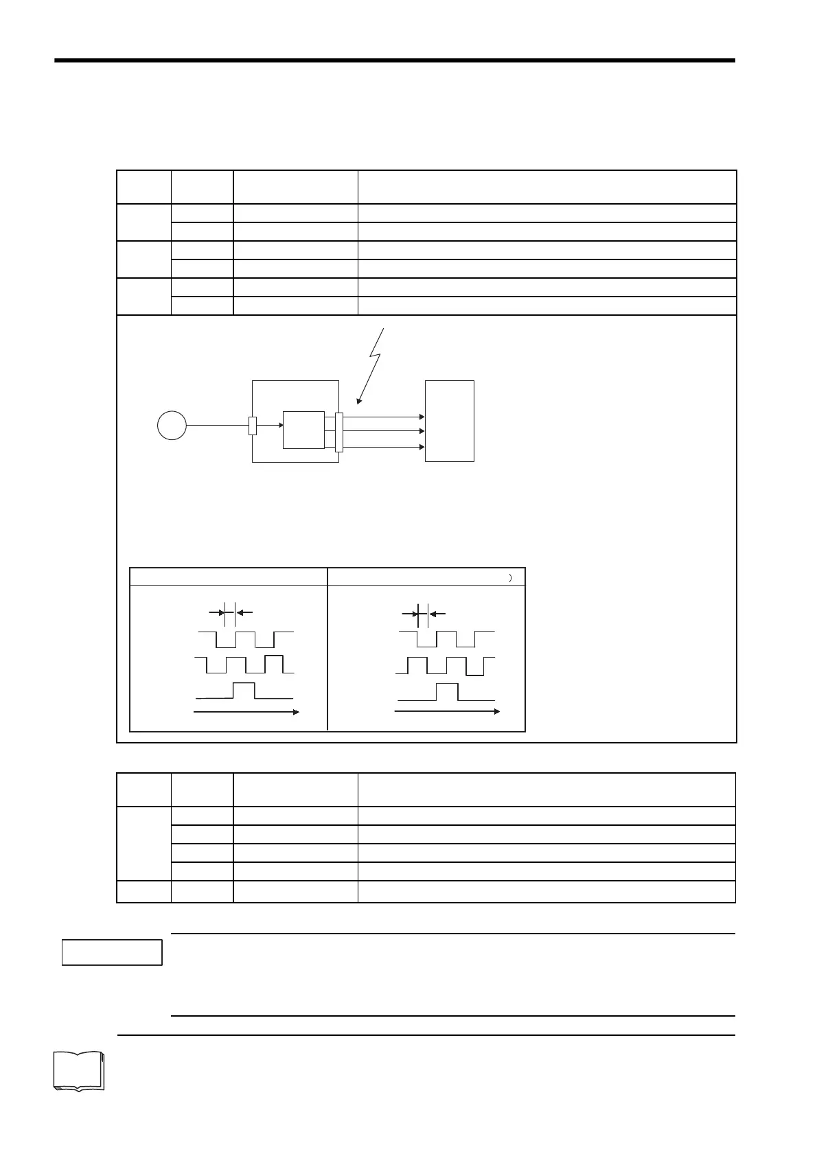
Encoder feedback pulses processed inside the SERVOPACK can be output externally.
The following signals are added when using an absolute encoder.
* SG (CN1-1, 2): Connect to 0 V on the host controller.
If using the SERVOPACK’s phase-C pulse output for a zero point return, rotate the servomotor twice or
more before starting a zero point return. If the configuration prevents the servomotor from rotating the ser-
vomotor or more, perform a zero point return at a motor speed of 600 min
-1
or below. If the motor speed is
faster than 600 min
-1
, the phase-C pulse output may not be output correctly.
1
Dividing
The dividing means that the divider converts data into the pulse density based on the pulse data of the encoder installed on
the servomotor, and outputs it. The setting unit is the number of pulses/revolution.
Type Signal
Name
Connector
Pin Number
Name
Output PAO CN1-33 Encoder output phase A
/PAO CN1-34 Encoder output phase /A
Output PBO CN1-35 Encoder output phase B
/PBO CN1-36 Encoder output phase /B
Output PCO CN1-19 Encoder output phase C (zero-point pulse)
/PCO CN1-20 Encoder output phase /C (zero-point pulse)
* The pulse width of the zero-point pulse (phase C) is changed according to the setting of the dividing
1
ratio (Pn201). This
pulse width should be the same as that for phase A.
Output Phase Form
PG
SERVOPACK
CN2
CN1
Encoder
Host controller
Note: The width of the zero-point pulse varies
depending on the setting of the dividing
ratio (Pn201). The width of zero-point
pulse and phase A are identical.
These outputs explained here.
Phase A (PAO)
Phase B (PBO)
Phase C (PCO)
Serial data
Frequency
dividing
circuit
*
Phase A
Phase B
Phase C
90
˚
t
Phase A
Phase B
Phase C
90˚
t
Forward rotation (phase B leads by 90˚) Reverse rotation (phase A leads by 90˚
Type Signal
Name
Connector
Pin Number
Name
Input SEN CN1-4 SEN Signal Input
SG CN1-2 Signal Ground
BAT (+) CN1-21 Battery (+)
BAT (-) CN1-22 Battery (-)
Output
SG
∗
CN1-1 Signal Ground