xiii
Notation Used in this Manual
Notation for Reverse Signals
The names of reverse signals (i.e., ones that are valid when low) are written with a forward slash (/)
before the signal abbreviation.
Notation Example
BK
is written as /BK.
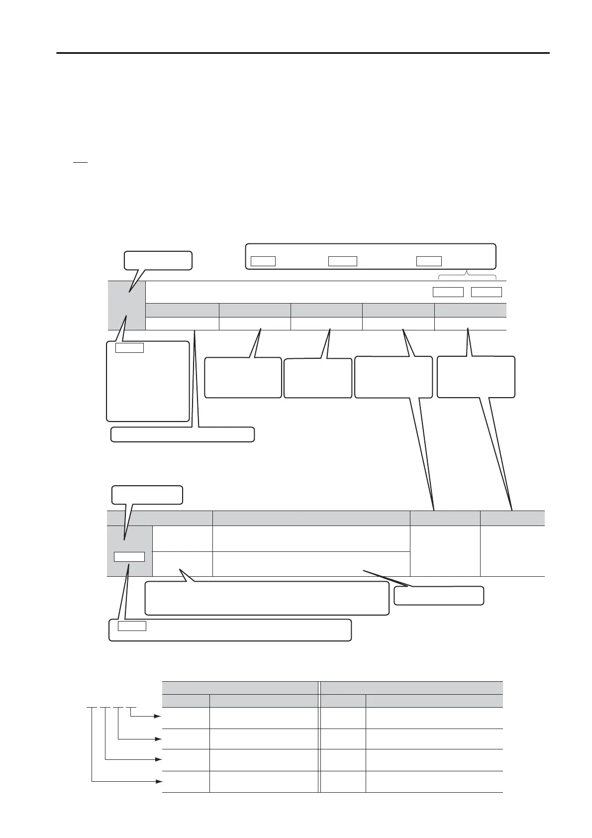
Notation for Parameters
The notation depends on whether the parameter requires a numeric setting (parameter for numeric
setting) or requires the selection of a function (parameter for selecting functions).
•
Parameters for Numeric Settings
Notation Example
n.0
(default setting)
Do not detect preventative maintenance warnings.
n.1
Detect preventative maintenance warnings.
Parameter Meaning When Enabled Classication
After restart Setup
This is the setting range for the parameter.
Pn00F
Parameter number
The notation “n.” indicates a parameter for selecting functions.
Each indicates the setting for one digit.
The notation shown here means that the first digit from the right is set to 1.
If All Axes is given here, the parameter applies to both axes A and B.
If you change the setting, the new setting will be applied to both axes.
Pn100
Speed Loop Gain
Position
Speed
Setting Range
10 to 20,000 0.1 Hz 400 Immediately
Setting Unit Default Setting When Enabled
Classication
Tuning
Parameter number
If All Axes is given
here, the parameter
applies to both axes A
and B.
If you change the
setting, the new setting
will be applied to both
axes.
All Axes
Position Torque
The control methods for which the parameters apply are given.
Speed
: Speed control : Position control : Torque control
This is the
parameter setting
before shipment.
This is when any
change made to the
parameter will
become effective.
This is the parameter
classication.
This is the minimum
unit (setting increment)
that you can set for
the parameter.
This column explains the
selections for the function.
•
Parameters for Selecting Functions
Notation Examples for Pn002
Pn002 =
n.
X
Indicates the rst digit from
the right in Pn002.
Pn002 =
n.
1
Indicates that the rst digit from
the right in Pn002 is set to 1.
Pn002 =
n.
X
Indicates the second digit
from the right in Pn002.
Pn002 =
n.
1
Indicates that the second digit from
the right in Pn002 is set to 1.
Pn002 =
n.
X
Indicates the third digit from
the right in Pn002.
Pn002 =
n.
1
Indicates that the third digit from
the right in Pn002 is set to 1.
Pn002 =
n.X
Indicates the fourth digit from
the right in Pn002.
Pn002 =
n.1
Indicates that the fourth digit from
the right in Pn002 is set to 1.
n.0 0 0 0
Notation
Digit Notation Numeric Value Notation
Meaning Notation Meaning

 Loading...


