3.4 Position Correction Table Settings
3.4.2 Position Correction Table Details
3
Position Correction Table
3-7
3.4.2
Position Correction Table Details
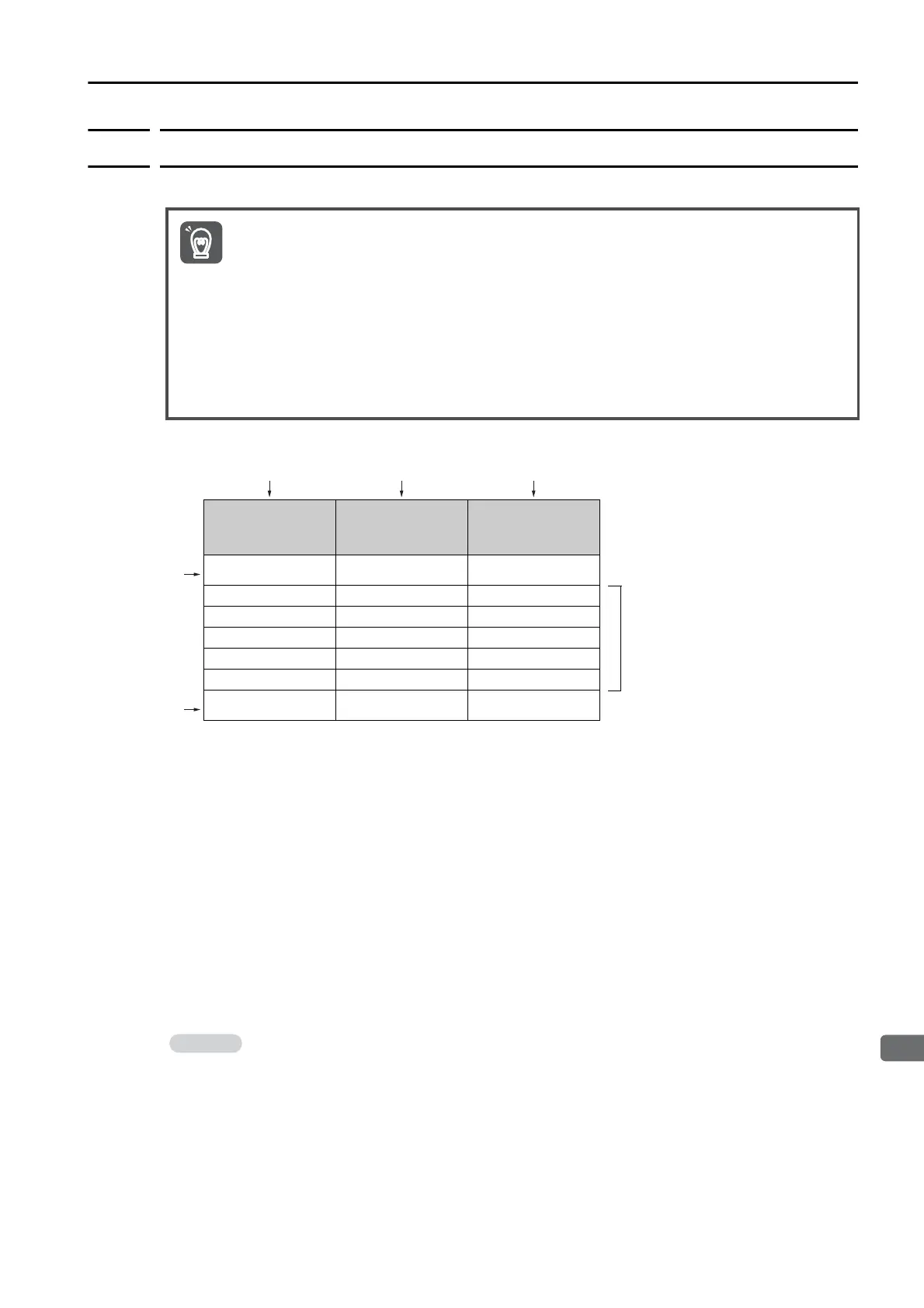
This section provides the following details on the Position Correction Table.
Example: Table entries is 7.
No.
Up to 128 table entries can be set.
Pre-correction Position
Enter the value of APOS (Feedback Position) of the master axis.
Note: For consecutive table numbers, the difference between the pre-correction positions and the difference
between the correction amounts cannot exceed 1,073,741,823 [reference unit].
Correction Value
Enter the numeric value which is the result of subtracting the feedback position value of the
master axis from the feedback position value of the slave axis.
Start and End Table Numbers
Enter a pre-correction position and adjustment amount for a position that exceeds the oper-
ating range.
If the operating range set in the Position Correction Table is exceeded, the correction cannot
be applied to the position and unstable operation may occur at the coordinate positions set
at both ends of the table.
Set the Position Correction Table as given below.
If the Position Correction Table is not set as given below, A.E94 (Position Correction Table Setting
Error) will occur, and the Position Correction Table cannot be written to the SERVOPACK.
• Ensure that the values for consecutive pre-correction positions in the Position Correction Table
satisfy the following condition: value of pre-correction position < value of next pre-correction
position.
• Ensure that the values for consecutive correction positions calculated by the Position Correc-
tion Table satisfy the following condition: value of correction position < value of next correction
position. The correction position is the reference position of the slave axis after correction (pre-
correction position + correction amount in Position Correction Table).
• Set the correction positions and correction amounts between -2,147,483,648 and
2,147,483,647.
No.
Pre-correction
Positions
[Reference unit]
Correction Value
[Reference unit]
1 -500,000 100
2 -400,000 100
3 -300,000 150
4 -200,000 250
5 -100,000 100
60-50
7 100,000 -50
• If the gantry cannot be moved to a position that exceeds the operating range due to the
mechanism, enter a value that exceeds the end of the operating range for the pre-correc-
tion position. In the above example, set the same correction amount as table numbers 2
and 6.
• Positions are corrected by performing linear interpolation on the correction amounts of the
positions between consecutive table numbers.
Important

 Loading...


